JPK Instruments NanoWizard
®
Handbook Version 2.2a
37
7. Artifacts
An ideal AFM image is an accurate representation of a sample surface. Every pa
an image that differs from the sample surface is an artifact
technique, scanning probe microscopy is not free of artifacts, so the micro
be able to recognize them to interpret his images properly. There are several
sources
of artifacts in AFM.
7.1 Tip shape issues
The shape of the AFM tip can have a drastic effect on the images that are
acquired. This is one area where having reproducible probes is an advantage, if
the tip shape is well characterized, so that the i
mages can be better interpreted,
and the obvious artifacts identified.
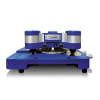
The following scheme gives an impression of how the tip shape can influence the
image of a given fea
ture on the sample. The feature taken here as an example is a
perfect rectangular
step on the surface. None of the tips shown produce an exact
image of the feature. The image is al
ways some combination of the tip shape and
the true surface topography.
The sharpest, narrowest tip produces the most
accurate representation of the surface.
A practical example is shown on the right. The AFM image shows a 3D view of a
red blood cell with protrustions on the surface. In fact, the rim of the cell is rather
steep and not shaped like a ramp as displayed in this imag
shape is caused by the edges of the pyramidal shaped cantilever.
Two parameters commonly used to model tip geometry are a cone angle of the
main pyramid that forms the tip, and an equivalent radius of the tip end. The
images of
small sharp features on the surface are dominated by the tip radius,
while the images of larger ones are dominated by the cone shape of the tip. The
cone angle of the tip also has an effect on the images of depressions in the
surface, changing the apparent
side angles and sometimes even preventing the tip
reaching the bottom of the depression. Regions with shallow features and a
gradient that changes gently are reproduced well by the tip, however.
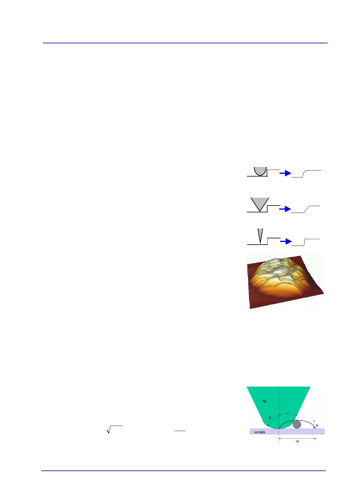
The relationship between the observed width W of a featu
the probe tip can be calculated for an idealized
tip shape, such as the one shown
here.
For
,
dRW 8=
and
For R = 10 nm and d = 5 nm, the observed width would be W = 20 nm