Once all assemblies have been completed, please review the follow-
ing suggestions before attempting initial flights.
• Review the instruction book and confirm that all assembly steps have
been completed thoroughly.
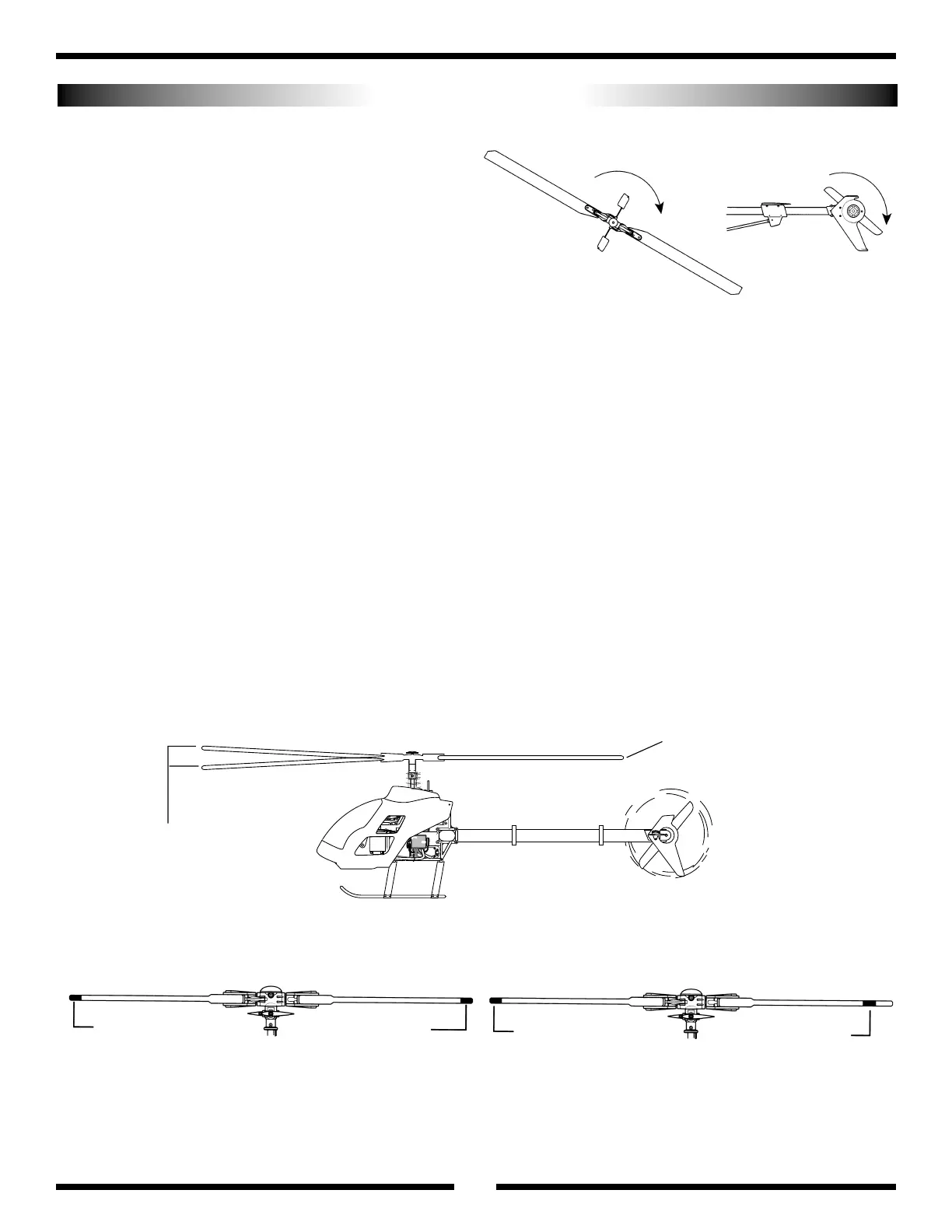
• Check to verify that the tail rotor assembly rotates in the correct direc-
tion (see the diagram below).
• Check to insure that all servos are operating smoothly and in the cor-
rect direction. Also verify that there is no binding in the control rods
and that each servo horn is secured with a servo horn mounting screw.
• Verify that the gyro is operational and compensating in the correct
direction (see page 48 for details).
• Make sure that both the transmitter and receiver have been fully charged
(refer to your radio system instructions for proper charging procedures).
FINAL PREFLIGHT CHECK
BLADE TRACKING IDENTIFICATION
A: Use two different blade-tracking tape colors (e.g., black and red) at the
tip of each main rotor blade.
B: Use the same color blade tracking tape located at different positions on
each rotor blade. Tracking tape is generally provided on the included
decal sheet.
Note: Adding blade-tracking tape to the rotor blades at this stage will
make it necessary to restatic balance the main rotor blades.
Blade Labeling for Tracking Purpose
BLADE TRACKING ADJUSTMENT
Blade tracking is an adjustment to the main rotor blade pitch that
must be accomplished during the initial test flights. Although the blade
pitch angle in each blade may appear equal, it is still possible for a set of
main rotor blades to run “out of track,” making adjustment necessary.
Main rotor blades that are out of track with one another can cause
vibration, instability, and a loss of power due to additional drag.
On the initial flight, it will be necessary to increase the blade speed to
just before lift-off rpm and view the rotor disc at eye level from a safe dis-
tance (approximately 15 to 20 feet) away from the models.
Note which blade is running low (by colored tracking tape) and
increase the pitch of the low blade one turn of the ball link at a time until
each blade runs in track (on the same plane).
Please refer to the diagrams below to identify the different tracking
situations, as well as several methods to mark each rotor blade for track-
ing identification.
Incorrect
Out of Track
Correct —
In Track
Caution: Be sure to maintain a safe distance from the helicopter
(15 to 20 feet) when tracking main rotor blades.
Adjustment is Necessary
Adjustment is NOT Necessary
A
Red
Black
B
Red
Black
Rotate the main rotor counterclockwise (backward) and
note the rotation direction of the tail rotor.
51
Correct Main/Tail Rotation direction