EasyManua.ls Logo

JR Vibe 90 3D User Manual

JR Vibe 90 3D
97 pages
To Next Page IconTo Next Page
Page #1 background imageLoading...
Page #1 background image
ASSEMBLY INSTRUCTIONS
VIBE 90 SPECIFICATIONS
Length: 54 in
Height: 17.5 in
Weight: 10.2-10.5 lb
Engine: .80–.91 Heli
Bearings: Full
Gear Ratio: 8:1:4.83
Main Blade: 700–720 mm
(Main rotor blades not included)
7749
7/2005
®
Designed for Today’s
Extreme 3D Flying

Table of Contents

Question and Answer IconNeed help?

Do you have a question about the JR Vibe 90 3D and is the answer not in the manual?

JR Vibe 90 3D Specifications

General IconGeneral
BrandJR
ModelVibe 90 3D
CategoryToy
LanguageEnglish

Summary

Vibe 90 Introduction and Features

Frame Assembly Features

Details new carbon fiber servo mounts, radio/gyro trays, and tank mounts.

Drivetrain Enhancements

Highlights new start shaft, bearings, and aluminum pinion block.

Rotor Head Design

Describes the no-bind swash design and 3D center hub.

Tail Rotor Improvements

Covers heavy-duty tail rotor hub and re-engineered gear case.

Canopy Design

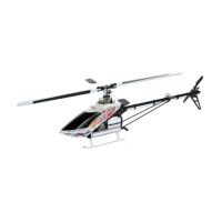
Features 3D dynamic canopy for drag reduction and multi-color finish.

Required Items for Assembly

Radio System Requirements

Specifies 6-channel or greater R/C helicopter system with 120°/140° CCPM.

Engine Requirements

Requires a .90-.91 R/C helicopter engine and special helicopter muffler.

Tools Needed for Assembly

Lists essential tools like screwdrivers, nut drivers, and pliers.

Field Equipment Required

Lists necessary field equipment like electric starter and batteries.

Hardware Identification

Hardware Identification Guide

Outlines the various screws, nuts, and washers included in the kit.

Core Assembly Steps

Clutch Bell/Start Shaft Assembly

Step-by-step instructions for assembling the clutch bell and start shaft.

Main Frame Assembly: Bearing Block/Clutch Installation

Attaching bearing blocks and clutch to the main frame.

Main Drive Gear/Autorotation Assembly

Assembling the main drive gear and autorotation unit.

Landing Gear Assembly Installation

Attaching the landing gear struts and skids to the frame.

Rotor Head and Tail Assembly

Swashplate Assembly

Detailed assembly of the swashplate components.

Rotor Head Installation

Attaching the main rotor head assembly.

Tail Drive Shaft Assembly

Assembling the tail drive shaft components.

Tail Boom/Bevel Pinion Gear Installation/Adjustment

Installing and adjusting the tail boom and pinion gear mesh.

CCPM Setup and Radio Configuration

Radio System Preparation

Steps for preparing the transmitter before setup.

Understanding CCPM Control Systems

Explanation of how CCPM swashplate mixing works.

CCPM Software Activation and Initial Adjustment

Guide to activating CCPM and initial radio setup.

Final Servo Adjustment and Radio Setup

Final tuning and setup of servos and radio system.

Final Assembly and Preflight Checks

Body Attachment & Final Fitting

Mounting and fitting the helicopter body.

Main Rotor Blade Attachment

Steps for attaching the main rotor blades.

Blade Tracking Adjustment

Adjusting main rotor blade tracking for stability.

Assembly Processes (P-x)

Assembly Process – Main Rotor Head 1

Steps for assembling the main rotor head components.

Assembly Process – Washout Unit

Detailed assembly of the washout unit.

Assembly Process – Tail Slide Ring

Assembling the tail slide ring mechanism.

Radio Data Sheets

XP8103 Vibe 90 3D Data Sheet, 120° CCPM

Radio setup data for XP8103 system, 120° CCPM.

XP9303 Vibe 90 3D Data Sheet, 140° CCPM

Radio setup data for XP9303 system, 140° CCPM.

10X Vibe 90 3D Data Sheet, 120° CCPM

Radio setup data for 10X system, 120° CCPM.

10X Vibe 90 3D Data Sheet, 140° CCPM

Radio setup data for 10X system, 140° CCPM.

Vibe 90 3D Warranty Information

VIBE 90 3D WARRANTY INFORMATION

Details of the product warranty and return policy.

Related product manuals