1-1
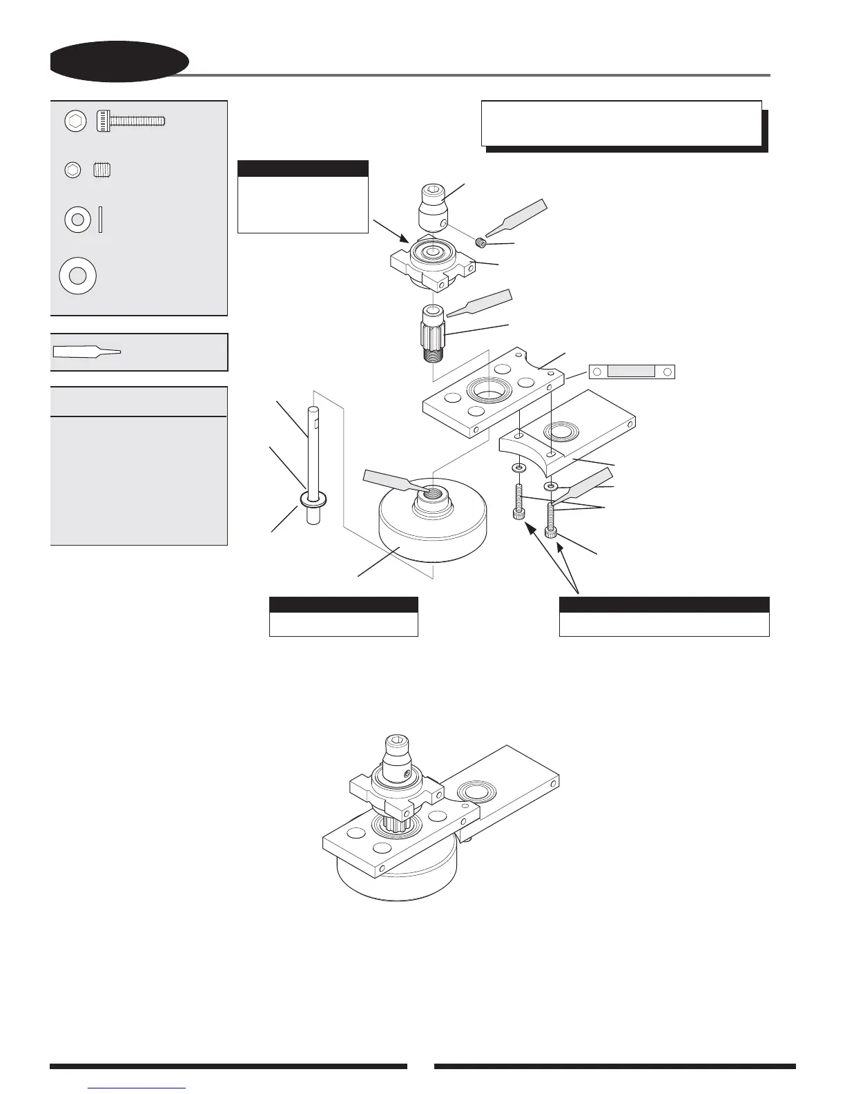
CLUTCH BELL/START SHAFT ASSEMBLY
Socket Head Bolt, 3 x 14 mm
...2 pcs
...................1 pc
...................1 pc
....................2 pcs
Starter Hex
Adaptor
Set Screw,
4 x 4 mm
Start Shaft
Bearing Block
Pinion Gear
Long Bearing Block “A”
Long Bearing Block “B”
Flat Washer, 3 mm (2 pcs)
Socket Head Bolt,
3 x 14 mm (2 pcs)
Clutch Bell Assembly
Start Shaft
Set Screw, 4 x 4 mm
Flat Washer, 3 mm
Thin Washer, 6 x 8 mm
Complete Assembly
Thin Washer
6 x 8 mm
Be sure the bearing
with the 6 mm ID
faces upward.
Use Red & Green
Threadlock
TEAM TIP: Clean areas with rubbing alcohol to
remove any oil residue before applying threadlock.
Use Green Threadlock
Note:
Position so that
bearing is at
the top of the
bearing block.
Green
Green
Red
Apply Red Threadlock
& Tighten at Step 3-8
Red
Lightly Oil
Assembly Order:
1. Attach pinion to clutch bell
2. Attach clutch bell to
bearing block “A”
3. Attach start shaft bearing
block to pinion
4. Assemble start shaft
assembly
5. Attach bearing block “B”
Do not fully tighten at this time.
Note:
Note:

 Loading...


