2-3
2-4
JR
PR
O
PO
JR PR
O
PO
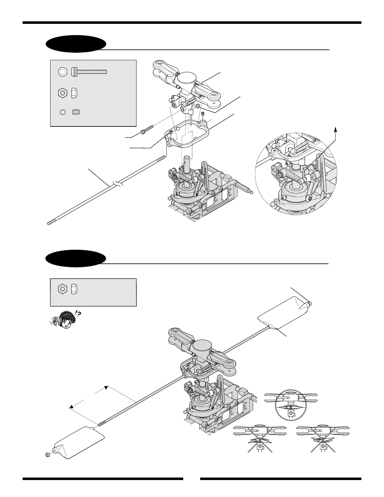
Rotor Head Assembly
3 mm Lock Nut
Flybar Control Arm
3 x 8 mm Socket Head Bolt
3 x 4 mm Set Screw
Flybar
........... 1 pc
.................................... 1 pc
................................. 2 pcs
3 x 18 mm Socket Head Bolt
3 mm Lock Nut
3 x 4 mm Set Screw
.................................. 2 pcs
3 mm Lock Nut
3 mm Lock Nut
Flybar Paddles (2)
IncorrectIncorrect
80 mm
JR Propo
JR Propo
12
Rotor Head Installation
Flybar Paddle Installation
In this step, secure the flybar temporarily
using the 3 x 4 mm set screws. The flybar
will be adjusted in Step 2-5 so that both
sides of the flybar are of equal length.
Be sure that the antirotation
pin located at the bottom of
the main rotor head fits into
the slot of the washout base.
It is very important to insure that the 2 flybar pad-
dles are parallel to each other, as well as to the
flybar control arm assembly.
Insert the flybar paddle 80 mm onto the flybar,
then secure with the 3 mm lock nuts (2) provided.
Be sure to note the correct direction of the flybar
paddle as shown in the diagram. When correctly
installed, the words “JR Propo” should face upward.
Alignment