1-3
1-4
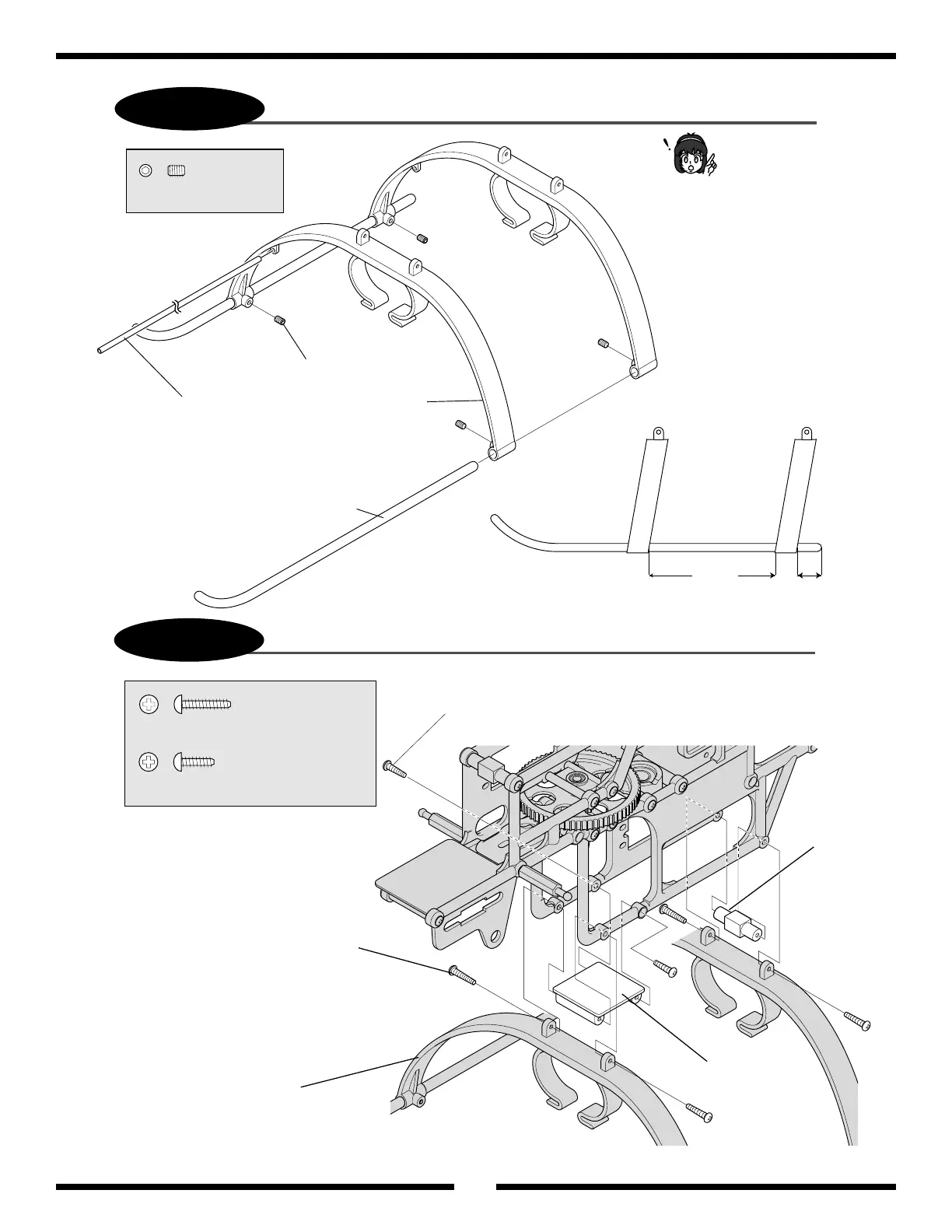
90 mm
15 mm
Landing Strut (2)
Landing Skid (2)
Antenna Tube
3 x 4 mm Set Screw (4)
.................. 4 pcs
3 x 4 mm Set Screw
2.6 x 8 mm Self Tapping Screw
2.6 x 15 mm Self Tapping Screw
Landing Strut (2)
Gyro Mounting Plate
Plastic Frame
Standoff
................................. 4 pcs
2.6 x 15 mm Self Tapping Screw
....................................... 2 pcs
2.6 x 8 mm Self Tapping Screw
10
Landing Gear Assembly
Landing Gear Attachment
Do not over tighten the
four 3 x 4 mm set screws
as it can damage the
landing struts.
Refer to the diagram below for
proper positioning when assem-
bling the landing gear assembly.
Attach the completed landing gear
assembly to the main frames as shown.