4-1
4-2
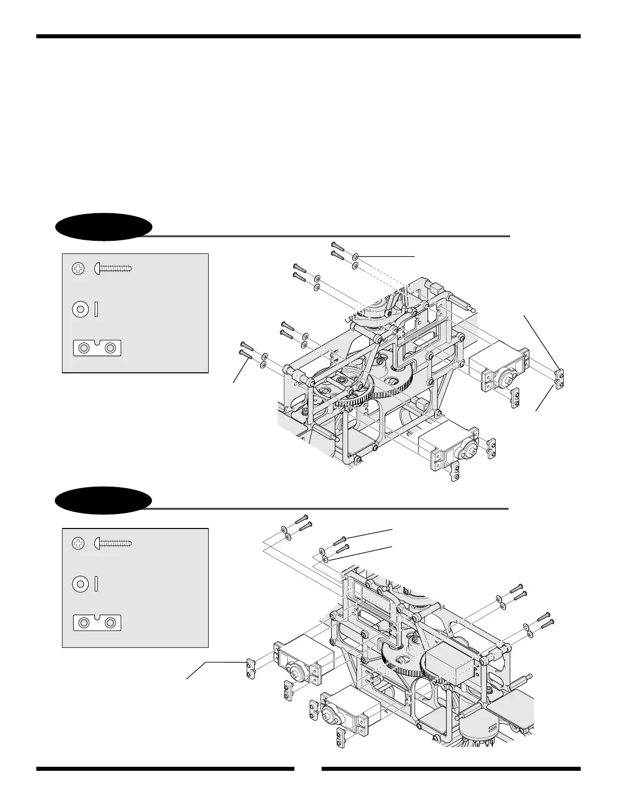
........................8 pcs
2.6 x 12 mm Self Tapping Screw
.......................................... 8 pcs
2.6 mm Flat Washer
..................... ........ 4pcs
Servo Mounting Plate
2.6 mm Flat Washer (8)
Servo Mounting Plate (4)
Long Flange
towards servo
2.6 x 12 mm Self Tapping Screw (8)
....................... 8 pcs
2.6 x 12 mm Self Tapping Screw
......................................... 8 pcs
2.6 mm Flat Washer
.............................. 4 pcs
Servo Mounting Plate
Servo Mouting Plate (4)
2.6 x 12 mm Self Tapping Screw (8)
2.6 mm Flat Washer (8)
L
F
R
Rudder
19
Aileron/Elevator Servo Installation (Standard Servos)
Pitch/Rudder Servo Installation (Standard Servos)
Servo Installation and Linkage Suggestions
• Use caution not to overtighten the servo mounting screws. The servos
should be able to be moved slightly within the grommets so that they
have a slight amount of
vibration absorption.
• Note the correct direction of the servo output shaft as shown in the
diagrams. If the servos are installed in the incorrect direction, the
linkages will not connect properly.
• Check to insure that all control rods have been adjusted to the proper
lengths as shown in the manual.
• Install the receiver, gyro, and speed controller using double-sided servo
tape as suggested. Please make sure that the cases of these components
do not come in direct contact with other parts of the model.
• Bundle all wires neatly using nylon ties as recommended. Check to
make sure that they cannot become tangled in the gearing or moving
control system parts of the model.
Note: Fit the long flanged portion of the servo
mounting plate B into the rubber servo grommets.
Fit the long flanged portion of the servo mounting
plate B into the rubber servo grommets.