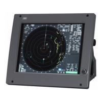
SECTION 11
SPECIFICATION
11.1 JMA-9172-SA TYPE RADAR............................................................... 11-1
11.2 SCANNER UNIT (NKE-1532) ...............................................................11-2
11.3 DISPLAY UNIT (NCD-9170) .................................................................11-3
11.4 Target Tracking Function ...................................................................11-6
11.5 AIS FUNCTION .....................................................................................11-7
Appendix A
NQE-3141 Interswitch Unit
A.1 OVERVIEW ............................................................................................A-1
A.1.1 Overview ......................................................................................... A-1
A.1.2 Interswitch Setup ........................................................................... A-1
A.2 INTERSWITCH OPERATION ................................................................ A-3
A.2.1 Operation Flow ............................................................................... A-3
A.2.2 Inter Switch Menu ...........................................................................A-4
A.2.3 Change of Connection Pattern (with 2 Display Units) ................ A-6
A.2.4 Change of Connection Pattern (with 3 or More Display Units) .. A-7
A.2.5 Operating Connection Pattern Files (File Operations) ............... A-8
A.2.6 Names of Display Units and Scanner Units ................................. A-9
A.3 REFERENCE ....................................................................................... A-10
A.3.1 Preheat Time after Change of Connection Pattern ................... A-10
A.3.2 Notes on Changing Connection Pattern .................................... A-10
A.3.3 Notes on Connecting Slave Display Unit ................................... A-10
A.3.4 Setting at Installation ................................................................... A-11
Appendix B
DRAWINGS
B.1 Interconnection Diagram of Display Unit ........................................... B-1
B.1.1 NCD-9170 ........................................................................................B-2
B.1.2 NCD-9170T ...................................................................................... B-3
B.1.3 NWZ-178-R ...................................................................................... B-4
B.1.4 NWZ-178-RT .................................................................................... B-5
B.1.5 NCE-5322-R ..................................................................................... B-6
B.1.6 NCE-5322-RT ................................................................................... B-7
B.2 Power System Diagram of Display Unit ............................................. B-8
B.3 Signal Flow Diagram of Display Unit .................................................. B-9

 Loading...