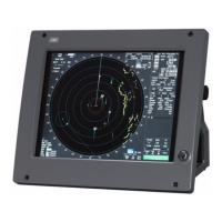
DRAWINGS
B.1 Interconnection Diagram of Display Unit ........................................... B-1
B.1.1 NCD-9170 ........................................................................................B-2
B.1.2 NCD-9170T ...................................................................................... B-3
B.1.3 NWZ-178-R ...................................................................................... B-4
B.1.4 NWZ-178-RT .................................................................................... B-5
B.1.5 NCE-5322-R ..................................................................................... B-6
B.1.6 NCE-5322-RT ................................................................................... B-7
B.2 Power System Diagram of Display Unit ............................................. B-8
B.3 Signal Flow Diagram of Display Unit .................................................. B-9
B.4 Primary Power System Diagram ....................................................... B-10
B.5 Block Diagram of Scanner Unit ........................................................ B-11
B.5.1 NKE-1532 ...................................................................................... B-12
B.6 Interconnection Diagram of Scanner Unit ....................................... B-13
B.6.1 NKE-1532 (AC110V) ...................................................................... B-14
B.6.2 NKE-1532 (AC220V) ...................................................................... B-15
B.7 Terminal Board Connection Diagram ............................................... B-16
B.7.1 JMA-9172-SA ................................................................................ B-17
Appendix B
DRAWINGS

 Loading...