INSTALLATIONS
2-64
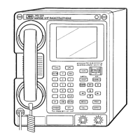
2.2.10.2 Connecting the signal lines
• Back of DPU-414
• Back of MF/HF controller (NCM-2150)
Remove the serial connector cover and the cover
over the printer power source. Then connect the
printer connection cable and the printer power
cable.
After connecting the power cable, fix it with the
cable clamp and replace the cover over the printer
power source.
Note) When the DPU-414 is installed, set the
printer power supply to 6.5V (factory
default). For details of the printer power
supply setting, see the NKG-800 section.
Printer cable
GND
Printer power cable
DC 6.5 V, 2 A
-
+
Printer cable:
7ZCJD0254A
(1.5 m)
Printer power cable:
7ZCJD0257C (1.5 m)
DC 6.5 V
max. 2 A
(for printer)
Serial connector cover
Printer power cover
Cable clamp

 Loading...