– 76 –
Brown
Orange
Yellow
Green
Blue
Perple
Gray
White
Light blue
Pink
Black
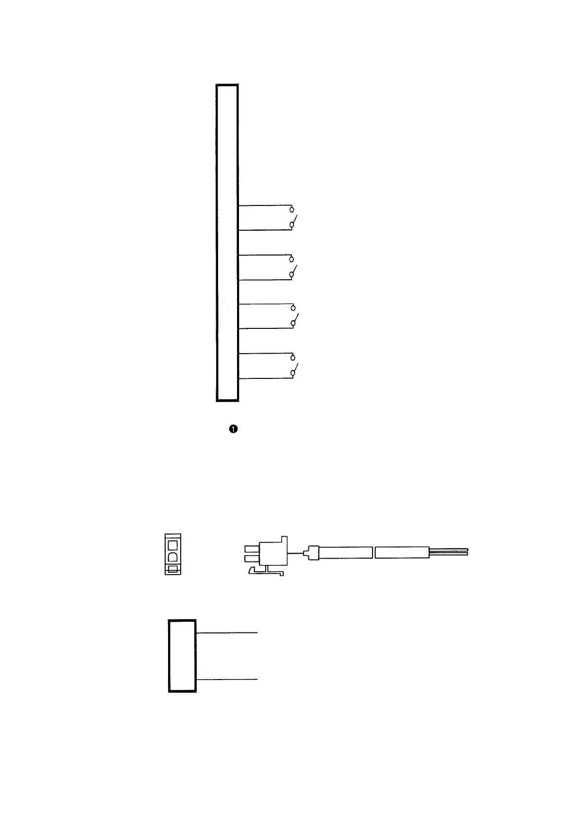
2) Wiring diagram of fixing max. speed
o Insert to the connector (connector CN39) of standing sewing machine pedal in the PSC box and use it.
(Caution) In case of decreasing the speed of switch for high-speed, use the variable resistor for max.
speed limit mounted on the control panel.
(2) Relay cord A asm. for DC24V (Part No. M9703351AA0)
Wiring diagram
o Before usage, insert it in the yellow or yellow-marked 24V DC connector (CN120 2P) of the PSC box.
* Reference for use is approximately one piece of
solenoid valve.
(Up to 100mA)
CN39
1
2
3
4
5
6
7
8
9
10
11
12
CN120
DC24V
GND
1
2
5V
Variable resistor for speed
S GND
Switch for lifting presser foot
S GND
Switch for thread trimming
S GND
Switch for high-speed
S GND
Switch for low-speed
S GND
1
2
Approx. 1.5m
 Loading...


