– 8 –
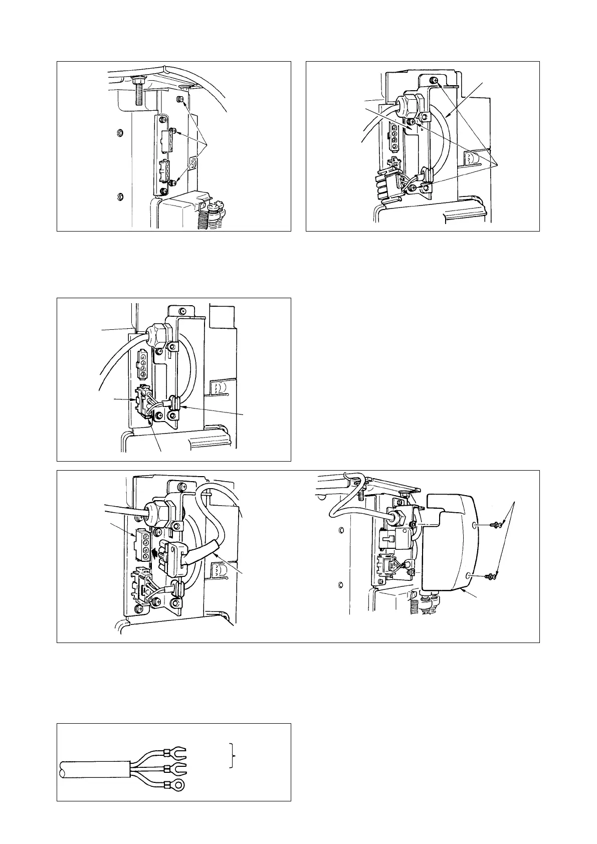
17) Connect connector
5
coming from the power
source cord to lower connector
6
after checking
the direction.
(Caution) When rubber bush
7
is off the install-
ing plate, adjust it to the groove of the
installing plate and insert it.
15) Remove three screws
1
located on the side of
the control box.
16) Set power source cord set
3
and installing
plate
4
supplied with the unit as accessories as
shown in the gure, and x them to the control
box main unit with three setscrews
2
which have
been removed.
18) Connect motor output cord
8
to connector
9
located on the side of the box.
19) Fix power source cover
!0
supplied with the unit using two screws
!1
supplied with the unit.
(Caution) At this time, be careful so that the motor output cord is not caught by the power source
cover and so that the cord enters the recess of the power source cover.
[ForCEspecicationsonly]
CE 1ø 230V
AC
220V-240V
1
3
8
4
2
7
5
6
9
!1
!0
20) Installing power switch
Connect power supply cord to the power switch.
[CEspecications]
Single phase 230V : Power supply cords :
Brown
,
Blue
,
and green/yellow (ground wire)
Brown
Blue
Green / Yellow
(ground wire)
 Loading...


