Redundancy Features ! 19
Chapter 1: E-series Overview
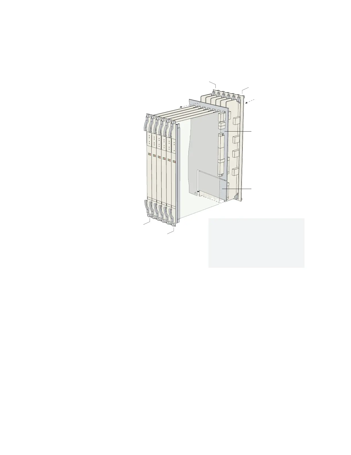
Figure 15: Data flow when a spare line module is active
For information about installing modules for line module redundancy, see
Chapter 5, Installing Modules. For information about configuring and managing SRP
module redundancy, see JUNOSe System Basics Configuration Guide, Chapter 5,
Managing Line Modules and SRP Modules.
Power
All E-series routers provide a power architecture that distributes redundant
–48 VDC feeds through the router to each line module, SRP module, and fan
module where DC-to-DC converters provide local conversion to the required
secondary voltages.
The ERX-310 router is available with either DC or AC power inputs. The AC-powered
version can be configured with one or two hot-swappable power supplies for
optional redundancy (see Figure 8 and Figure 9). The power supplies convert AC
power to internal –48 V redundant DC feeds that are then distributed through the
router.
Midplane
Redundancy
midplane
Spare line module
Primary line module
Redundancy
I/O module
Primary
I/O module
1. A packet arrives at the primary I/O module.
2. The packet passes along the redundancy
midplane from the primary I/O module to
the redundancy I/O module.
3. The packet passes from the redundancy
I/O module to the spare line module.
4. The spare line module processes the packet.
g013738