Replacing SFPs on GE I/O Modules ! 91
Chapter 9: Maintaining E-series Routers
! A ring that you press inward
! A bar that you pull sideways, then outward
! A tab that you pull sideways, then outward
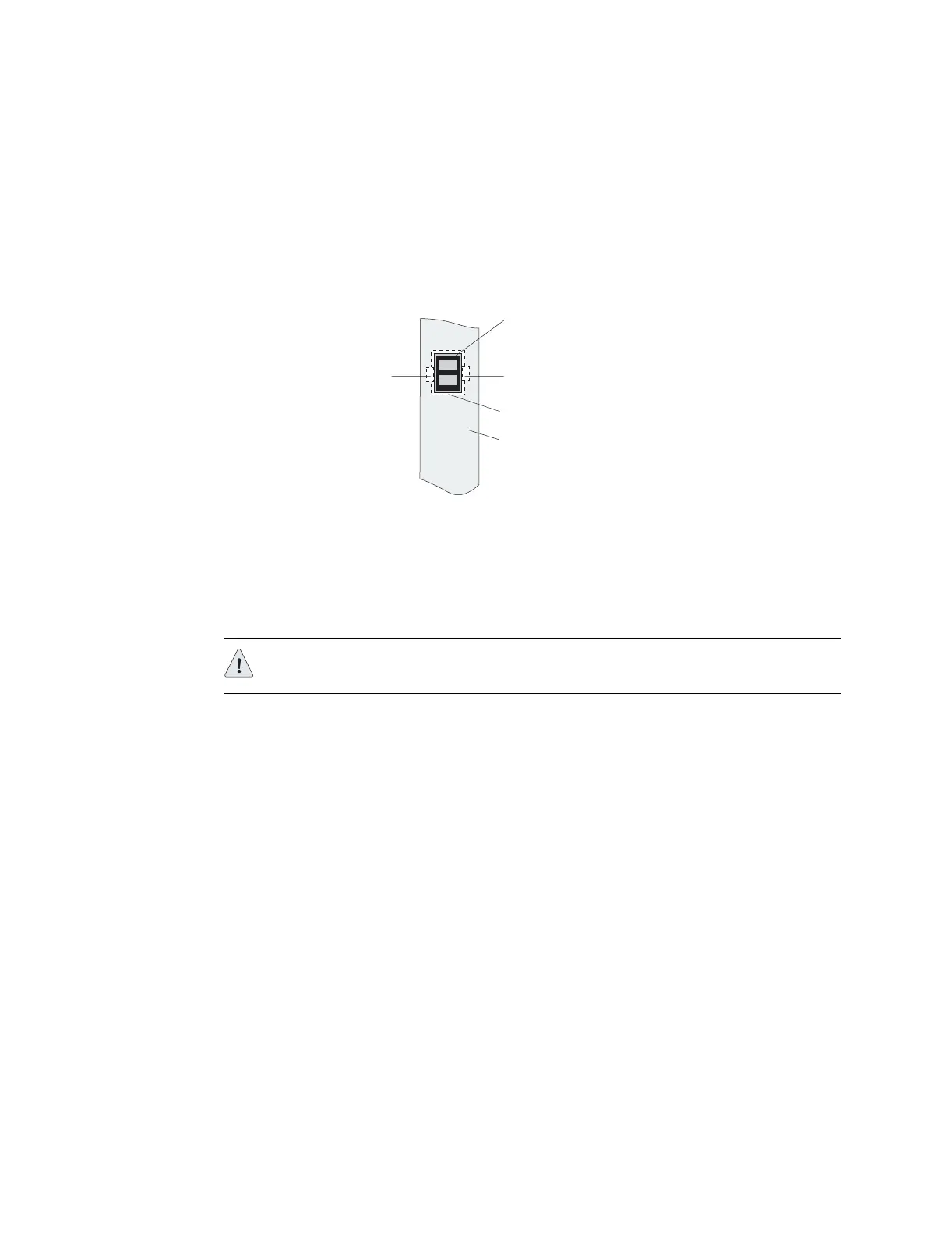
Figure 45: Possible release mechanisms on the SFP
5. Release the SFP and pull it out of the slot.
6. Place the SFP in an antistatic bag.
7. If you are using the redundant port on the E-series GE
I/O module, repeat steps
3 through 6 for the other SFP.
Installing SFPs
To install SFPs:
1. Put the antistatic wrist strap on your wrist, and connect the strap to the ESD
grounding jack on your system.
2. Identify the following items on the SFP (see Figure 46):
! The connection circuitry on the base
! The cable connectors on the front
The cable connectors will be protected by a dust cover.
Release bar, button,
or tab
Release ring
Transceiver
Release bar, button,
or tab
Module faceplate
g013435
CAUTION: For port redundancy to operate correctly, both the primary and
redundant ports on an E-series GE I/O module must use the same type of SFP.