E-series Hardware Guide
92 ! Replacing SFPs on GE I/O Modules
Figure 46: Example of SFP
3. Hold the SFP so that:
! The connection circuitry is adjacent to the TX and RX markings on the
module’s faceplate.
! The front will be visible when you install the SFP.
For a picture of the correct orientation, see Figure 47.
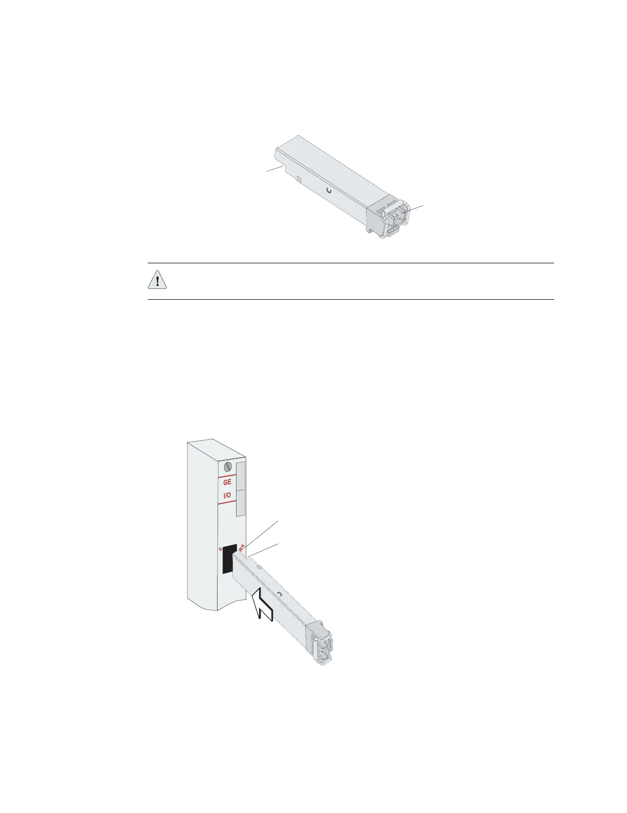
Figure 47: Installing an SFP on an E-series GE I/O module
4. Insert the SFP as far as you can into the I/O module.
The SFP should slide smoothly into the I/O module and should click into place.
If the SFP does not slide smoothly into the I/O module, check that the
orientation of the SFP is correct.
Cable connectors
on front
Connection circuitry
on base
g013436
CAUTION: Be sure to position the SFP correctly before you install it.
g013437
TX and RX markings on I/O module
Connection circuitry on base of SFP