Cabling the SRP I/O Module ! 59
Chapter 6: Cabling E-series Routers
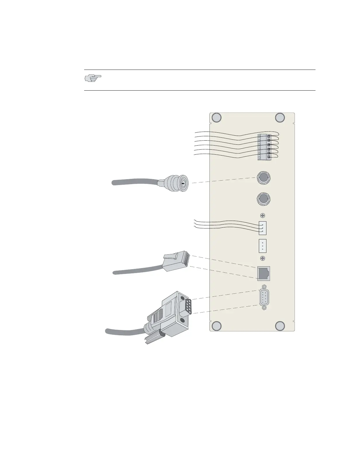
Figure 29: ERX-14xx model SRP I/O module
To connect the clock source input ports:
1. Depending on the connector type, complete one of the following tasks:
! E1: Attach the BNC connector to Clock A’s external timing port.
! T1: Wrap the tip wire on pin marked T of Clock A’s external timing port, the
ground wire on G pin, and the ring wire on R pin.
NOTE: Use shielded cables to connect the external clock sources to the clock
source input ports.
A
T
G
R
T1 100 OHM
CLOCK IN
B
T
G
R
E1 75 OHM
CLOCK IN
+
-
+
-
+
-
ALARMSEXTERNAL TIMING
CONSOLE
MINOR
MAJOR
CRITICAL
10/100
BASE T
RS-232
BNC (Europe)
DB-9
RJ-45
26-AWG wire
Wire-wrap connectors
(North America, Japan)
g013750