• Read
General Safety Guidelines and Warnings
, with parcular aenon to
Chassis and Component
Liing Guidelines
.
Ensure that you have the following parts and tools available:
• Number 2 Phillips (+) screwdriver (not provided)
• Eight screws to secure the mounng brackets to the rack (not provided)
• An ESD grounding strap (not provided)
• Recessed-mounng brackets to mount the switch in a recessed posion from the front posts of a
rack—2 (provided with the four-post rack-mounng kit)
• Flat head 4-40 Phillips screws to aach the recessed-mounng brackets to the side rails of the
bracket assembly—6 (provided with the four-post rack-mounng kit)
• Flat head 4x6-mm Phillips screws to aach the front-mounng bracket assembly to the chassis—12
(provided with the four-post rack-mounng kit)
To mount an EX4100 and EX4100-F switch in a recessed posion from the front posts of a 19-in. four-
post rack:
1. Remove the switch from the shipping carton (see "Unpack the EX4100 and EX4100-F Switch" on
page 119).
2. Place the switch on a at, stable surface.
3. Wrap and fasten one end of the ESD wrist strap around your bare wrist, and connect the other end
of the strap to a site ESD point.
4. Aach the recessed-mounng brackets provided with the four-post rack-mounng kit to the side
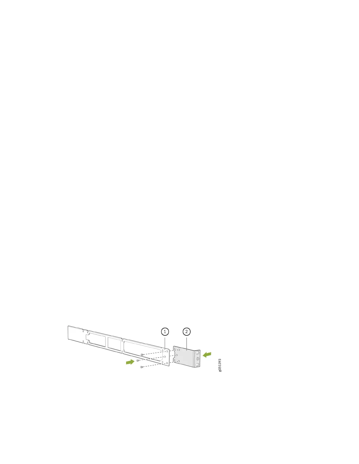
rails by using the at head 4-40 Phillips screws provided with the four-post rack-mounng kit .
Figure 76: Aach the Recessed-Mounng Bracket to the Side Rail
5. Align the recessed-mounng bracket assembly along the side panel of the switch.
131