6. Insert the at head 4x6-mm Phillips screws to aach the recessed-mounng bracket assembly into
the aligned holes on the chassis provided with the four-post rack-mounng kit and ghten the
screws.
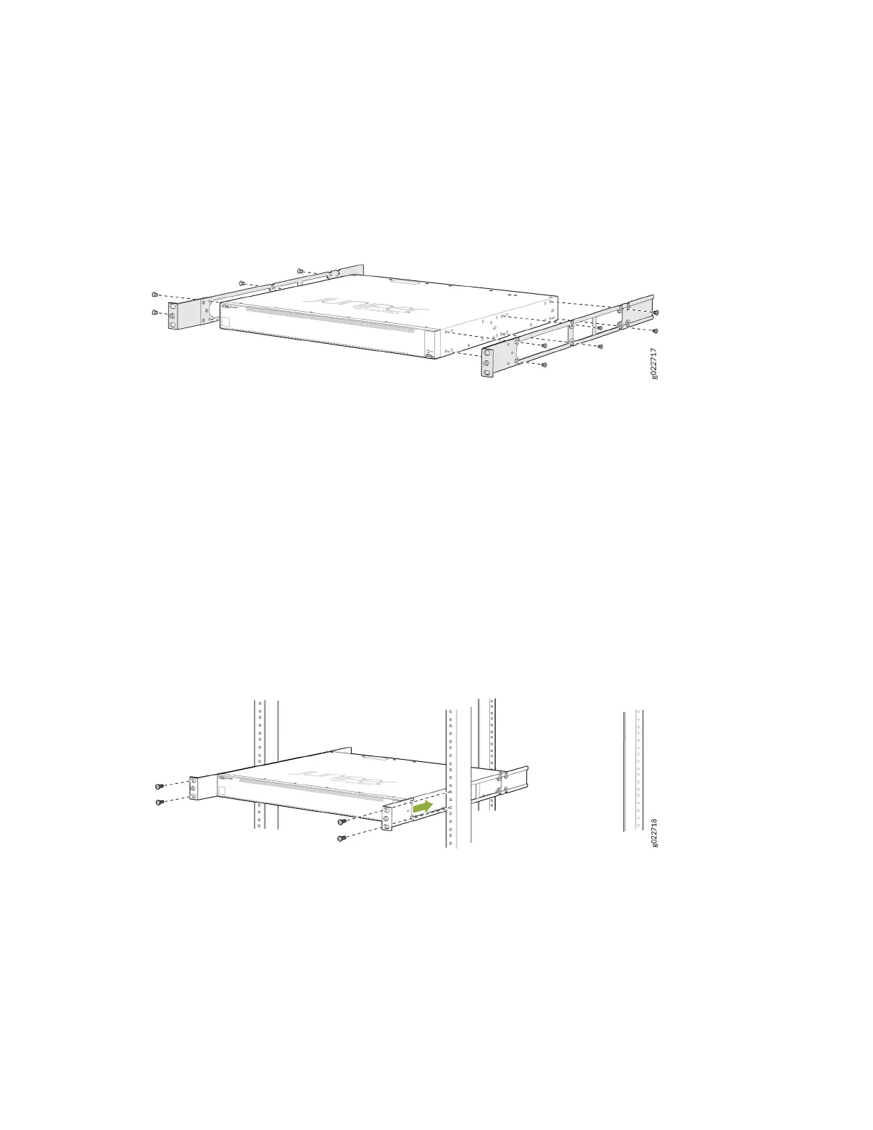
Figure 77: Aach the Recessed-Mounng Bracket Assembly to the Switch
7. Decide which end of the switch you want to place at the front of the rack. Posion the switch so
that the AIR IN labels on the fan modules are next to the cold aisle and the AIR OUT labels on the
fan modules are next to the hot aisle.
8. Have one person grasp both sides of the switch, li the switch, and posion it in the rack, aligning
the holes of the mounng brackets with the threaded holes in the front post of the rack. Have the
person align the boom hole in both the mounng brackets with a hole in each rack rail, making
sure that the chassis is level.
9. Have a second person secure the mounng brackets to the rack by using four screws appropriate
for your rack. Tighten the screws.
Figure 78: Secure the Switch to the Front Posts of a Rack
10. Slide the rear-mounng bracket blades into the side rails of the recessed-mounng bracket
assembly aached to the switch chassis.
11. Ensure that the chassis is level. Align the holes of the rear-mounng brackets with the threaded
holes in the rear post of the rack. Align the boom hole in both the mounng brackets with a hole
in each rack rail. Align the boom hole in both the rear-mounng brackets with the boom hole in
the front-mounng brackets.
132