c. Ensure that the pins are fully inserted into the terminal connector.
d. Use the screwdriver to ghten each screw on the terminal connector unl snug. Do not
overghten. Apply 4.5 lb-in. (0.51 Nm) of torque to the screws.
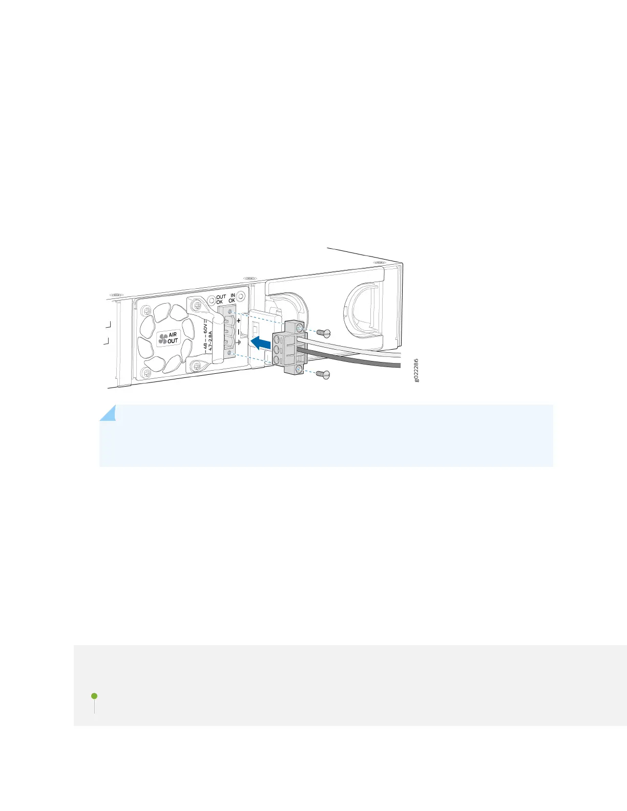
5. Insert the terminal connector (with the power cable aached) into the power supply socket on the
switch and secure it by ghtening the two screws on either side of the terminal connector (see Figure
91 on page 144).
Figure 91: Securing the Terminal Connector to the DC Power Inlet
NOTE: To supply sucient power, terminate the DC input wiring on a facility DC source that
is capable of supplying a minimum of 7.5 A at –48 VDC.
6. Connect the other end of the power cable to the power source.
7. Close the input circuit breaker.
8. Verify that the IN OK and the OUT OK LEDs are lit green and on steadily.
Connect the EX4100 and EX4100-F Switch to
External Devices
IN THIS SECTION
Connect a Device to a Network for Out-of-Band Management | 145
144