• Phillips (+) screwdriver, number 2
• Sloed (-) screwdriver
You install the power supply in the power supply slot in the rear panel.
WARNING: DC-powered switches are intended for installaon only in a restricted-
access locaon.
To connect DC power to the switch:
1. Ensure that the input circuit breaker is open so that the cable leads do not become acve while you
connect DC power.
NOTE: The DC power inlet in the switch has two terminals labeled + and – and has a terminal
to connect to earth ground.
NOTE: The + terminal is referred to as +RTN and the – terminal is referred to as –48 V in
DC
Power Wiring Sequence Warning
and
DC Power Electrical Safety Guidelines
.
2. Use the screwdriver to loosen the screws on the terminal connector.
3. Strip 0.25 inch (6.35 mm) of the insulator from one end of the power cable. Aach the two wires to
the wire pins.
4. Secure the wire pins to the appropriate terminals on the terminal connector by using the screws from
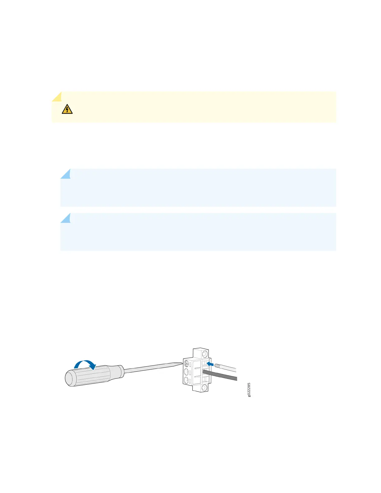
the terminal connector (see Figure 90 on page 143).
Figure 90: Securing Wire Pins to the Terminals on the Terminal Connector
• To connect the wire pins to the appropriate terminals on the terminal connector:
a. Connect the posive (+) wire pin to the + terminal on the terminal connector.
b. Connect the negave (–) wire pin to the – terminal on the terminal connector.
143