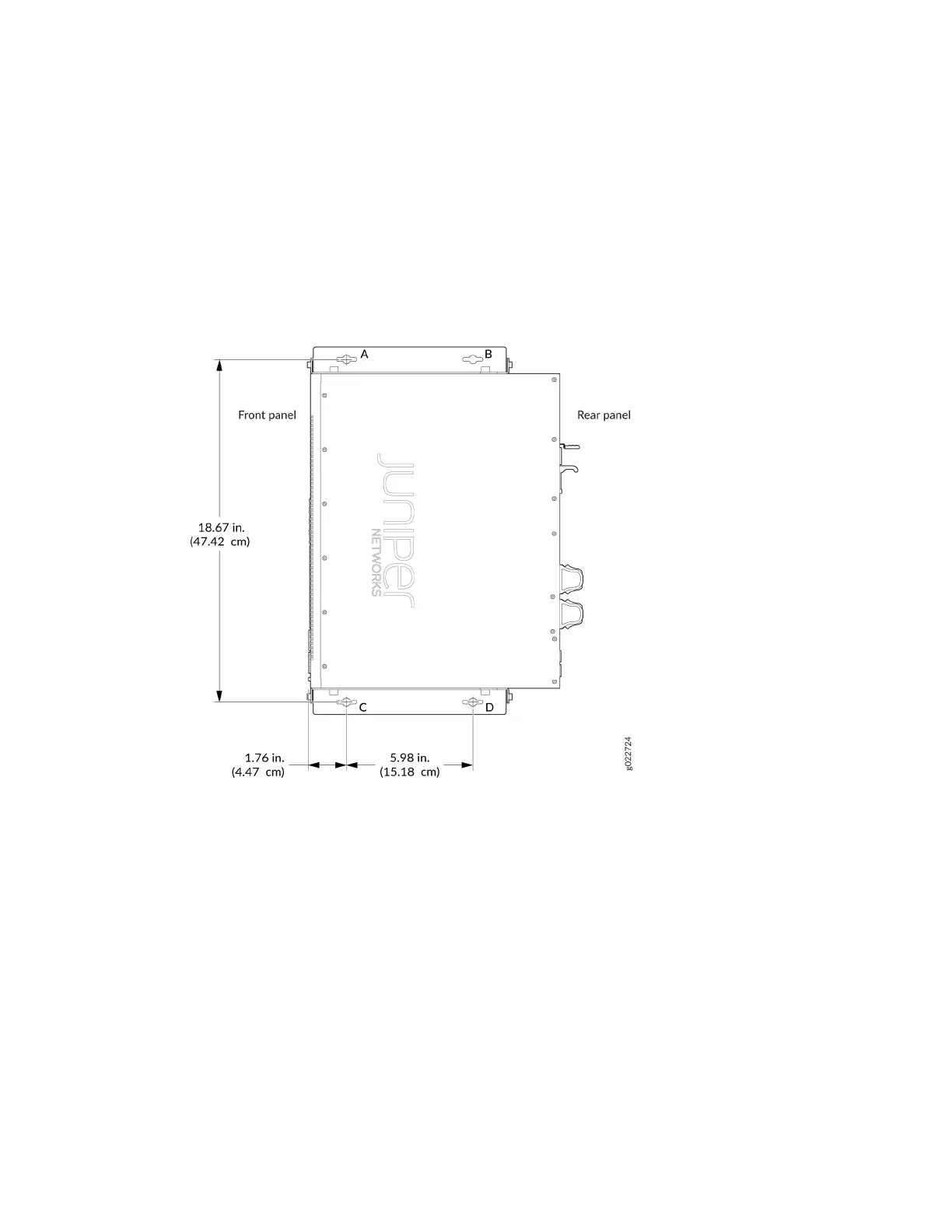
c. Drill a hole (C) at a distance of 18.67 in. (47.43 cm) on a plumb line down from screw A and install
a mounng screw.
d. Drill a hole (D) at a distance of 18.67 in. (47.43 cm) on a plumb line down from screw B and install
a mounng screw.
Figure 82: Measurements for Installing Mounng Screws
4. Place the switch against the wall such that the front panel of the switch faces to the right side and
the holes in the mounng bracket heads align with the mounng screw heads.
5. Slide the switch chassis to the le or right a bit so that the mounng screws are pushed into the
channels of the holes in the mounng brackets unl the switch rests rmly in place as shown in
Figure 83 on page 136.
135