2. Place the grounding lug aached to the grounding cable over the protecve earthing terminal on the
rear panel (see Figure 84 on page 138 and Figure 85 on page 138).
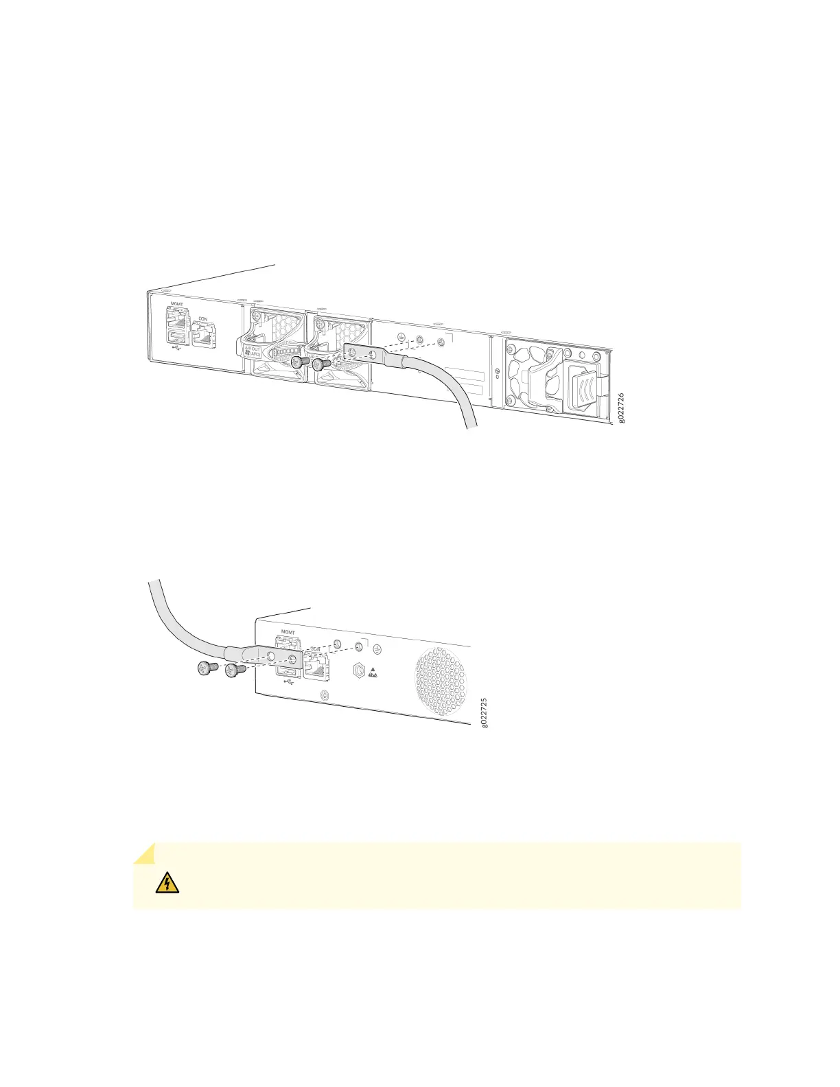
Figure 84: Connect a Grounding Cable to an EX4100-24P, EX4100-24T, EX4100-48P, EX4100-48T,
EX4100-24MP, and EX4100-48MP Switch
Figure 85: Connect a Grounding Cable to an EX4100-F-24P, EX4100-F-24T, EX4100-F-48P, and
EX4100-F-48T Switch
3. Secure the grounding lug to the protecve earthing terminal with the screws.
4. Secure the grounding cable and ensure that it does not touch or block access to other switch
components.
WARNING: Ensure that the cable does not drape where people could trip over it.
138