1—
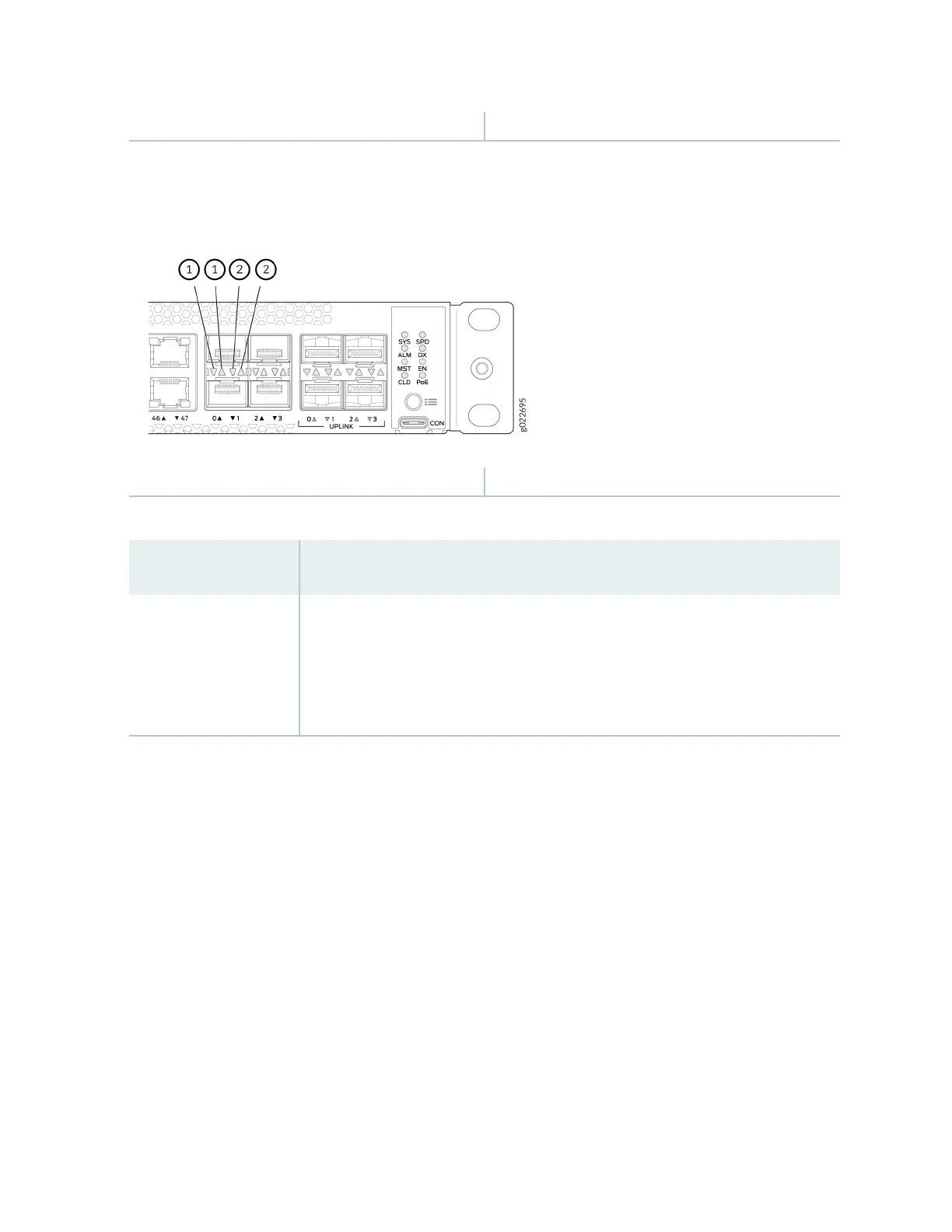
Link acvity LED
2—
Status LED
Figure 40: LEDs on the SFP+/SFP28 Virtual Chassis ports on EX4100 and EX4100-F Switches
1—
Link acvity LED
2—
Status LED
Table 9: Link Acvity LED on the Network Ports, Uplink Ports, and Virtual Chassis Ports
Link Acvity LED Color Link Status LED State and Descripon
Green
• On steadily—The port and the link are acve, but no link acvity is occurring.
• Blinking—The port and the link are acve, and link acvity is occurring.
• O—The port is not acve.
EX4100 and EX4100-F switches have network port mode LEDs (labeled SPD, DX, EN, and POE) on the
right side of the front panel (see Figure 41 on page 51). These LEDs indicate the status of the network
ports. Use the mode buon on the right side of the front panel to toggle the status LEDs. You toggle the
status LEDs to show the dierent port parameters for the network ports. The LED that is lit indicates
the port parameter. Table 10 on page 51 describes the status LEDs.
50