EasyManuals Logo

Juniper EX4100 User Manual

Juniper EX4100
283 pages
To Next Page IconTo Next Page
To Previous Page IconTo Previous Page
Page #88 background imageLoading...
Page #88 background image
EX4100 switch. Power supplies are installed in the power supply slots labeled PSU 0 and PSU 1 in the
rear panel of the chassis.
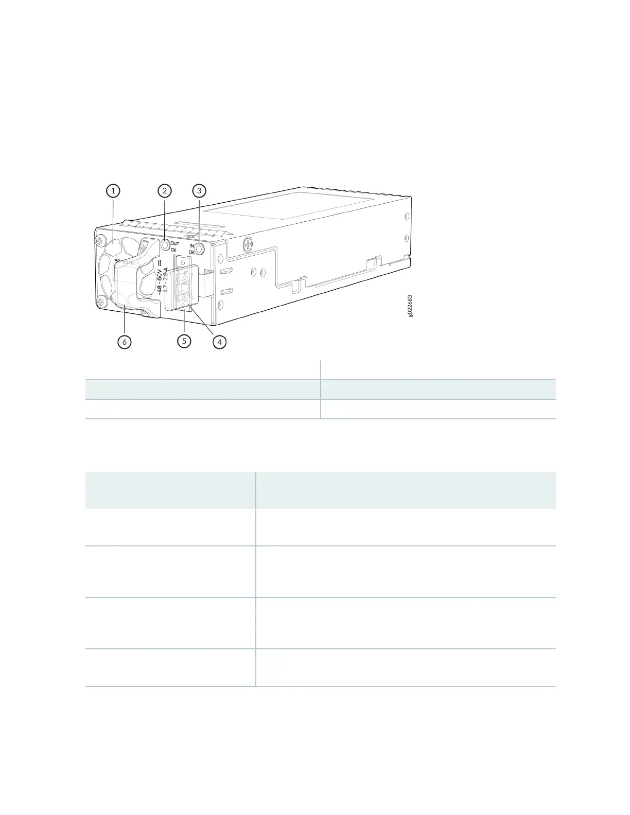
Figure 58: 150 W DC Power Supply for EX4100-48T-DC and EX4100-24T-DC
1
Power supply unit fan
4
Power supply unit ejector lever
2
Power supply unit LED
5
Power supply unit inlet
3
Power supply unit LED
6
Power supply unit handle
Table 22 on page 79 lists the details of the 150 W DC power supplies used in EX4100 switches.
Table 22: Details of the DC Power Supplies in EX4100 Switches
Details 150 W DC Power Supplies
Model number JPSU-150-DC-AFO
Minimum number of power supplies
installed in chassis
1
Maximum number of power supplies
installed in chassis
2
Power supply status LEDs IN OK and OUT OK
79

Table of Contents

Other manuals for Juniper EX4100

Questions and Answers:

Question and Answer IconNeed help?

Do you have a question about the Juniper EX4100 and is the answer not in the manual?

Juniper EX4100 Specifications

General IconGeneral
ModelEX4100
CategorySwitch
LayerLayer 2/3
Power ConsumptionVaries by model and configuration
PoEOptional
ManagementWeb UI, CLI, SNMP
Operating Temperature0°C to 45°C
Input Voltage100-240V AC
Storage Temperature-40°C to 70°C
Humidity5% to 90% non-condensing
DC Power Input-48V DC
JUNOS OSYes
Security FeaturesACLs
Layer 2 FeaturesVLAN, RSTP, MSTP, LACP
Layer 3 FeaturesStatic routing, OSPF
QoS8 queues per port

Related product manuals