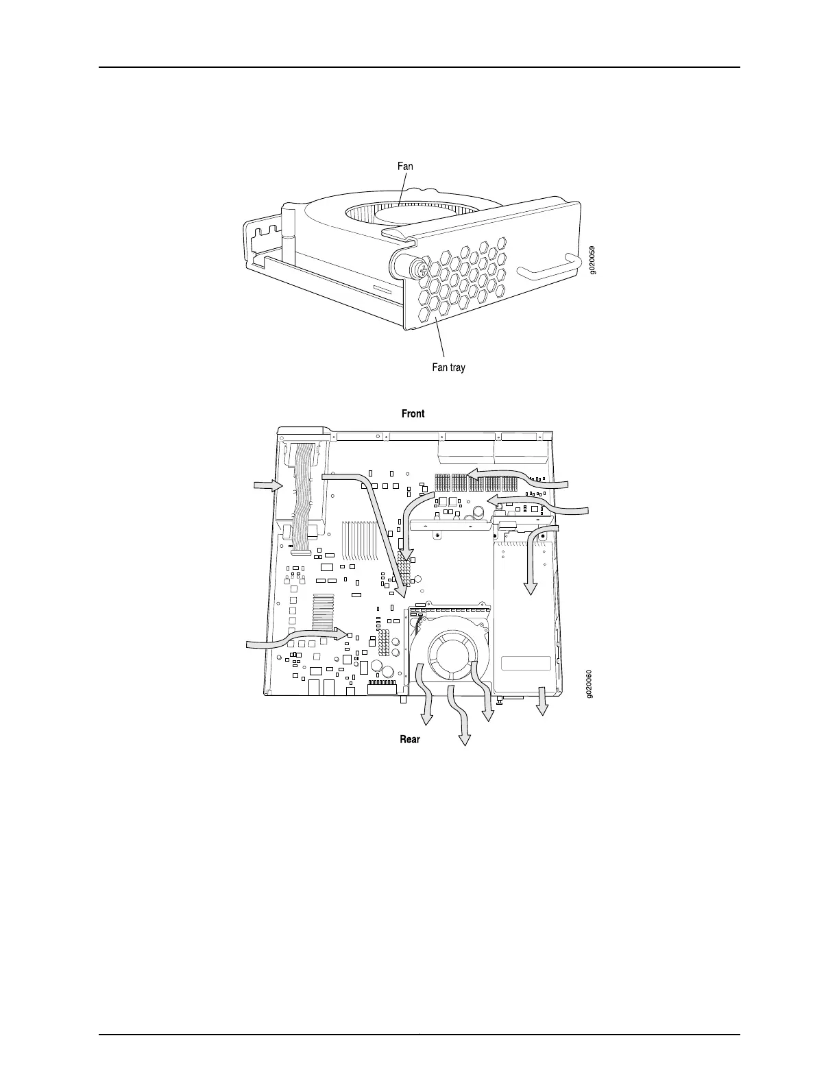
Figure 20: Fan Tray Used in an EX3200 Switch
Figure 21: Airflow Through the EX3200 Switch Chassis
Temperature sensors in the chassis monitor the temperature within the chassis. The
system raises an alarm if the fan fails or if the temperature inside the chassis rises above
permitted levels. If the temperature inside the chassis rises above the threshold, the
system shuts down automatically and the temperature shutdown LED on the rear panel
is lit. You can see the status of fans and the temperature from the Show Environment
Status option in the Status menu in the LCD panel.
Related Topics Field-Replaceable Units in EX3200 and EX4200 Switches on page 18•
• Rear Panel of an EX3200 Switch on page 8
• Prevention of Electrostatic Discharge Damage on EX Series Switches on page 236
• Installing a Fan Tray in an EX3200 or EX4200 Switch on page 133
Copyright © 2010, Juniper Networks, Inc.32
Complete Hardware Guide for EX3200 and EX4200 Ethernet Switches