Table 26: RJ-45 Connector Pinouts for the Services Gateway Ethernet
Port (1 Gbps) (continued)
SignalPin
BI_DC+4
BI_DC-5
BI_DB-6
BI_DD+7
BI_DD-8
Related
Documentation
Interface Cable and Wire Specifications for the SRX110 Services Gateway on page 71•
• RJ-45 Connector Pinouts for the SRX110 Services Gateway Console Port on page 73
• SRX110 Services Gateway Front Panel and Back Panel Views with 3G and Integrated
VDSL2 on page 9
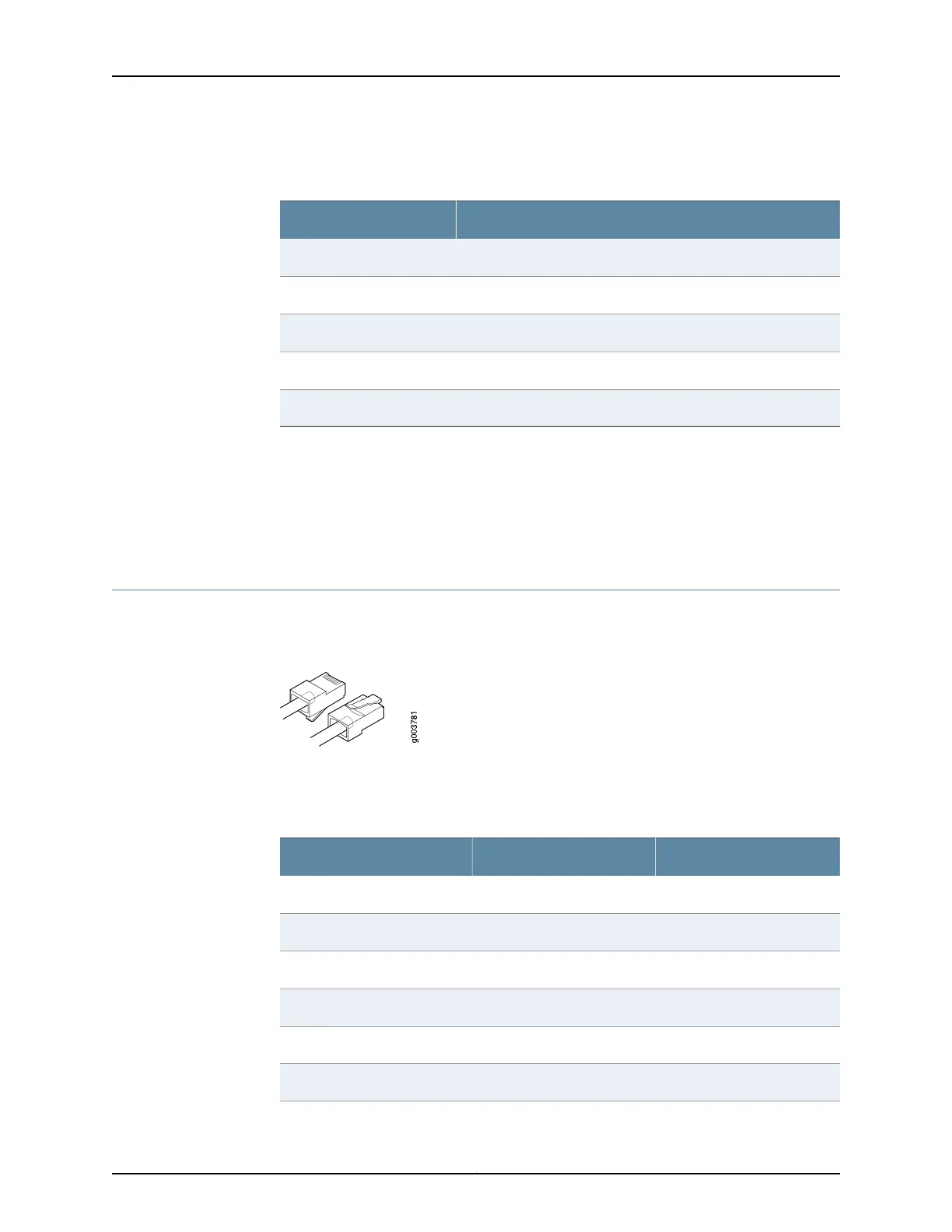
RJ-45 Connector Pinouts for the SRX110 Services Gateway Console Port
Figure 12 on page 73 shows the RJ-45 connector pinouts for the console port.
Figure 12: Console Cable Connector
Table 27 on page 73 describes the RJ-45 connector pinouts for the console port.
Table 27: RJ-45 Connector Pinouts for the Services Gateway Console
Port
DescriptionSignalPin
Request to SendRTS1
Data Terminal ReadyDTR2
Transmit DataTXD3
Signal GroundGround4
Signal GroundGround5
Receive DataRXD6
73Copyright © 2012, Juniper Networks, Inc.
Chapter 9: Interface Cable Specifications and Connector Pinouts