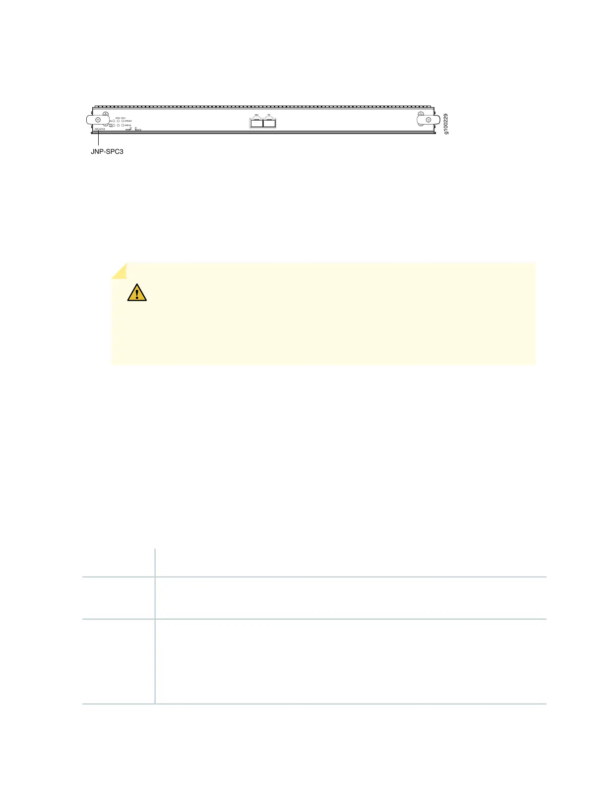
Figure 6: Services Processing Card SRX5K-SPC3
Each SPC consists of the following components:
•
SPC cover, which functions as a ground plane and a stiffener.
•
Two 10–Gigabit Ethernet small form-factor pluggable plus (SFP+) chassis cluster control ports for
connecting multiple devices into a redundant chassis cluster. See the Chassis Cluster User Guide for SRX
Series Devices for more information about connecting and configuring redundant chassis clusters.
CAUTION: If you face a problem running a Juniper Networks device that uses a
third-party optic or cable, the Juniper Networks Technical Assistance Center (JTAC)
can help you diagnose the source of the problem. Your JTAC engineer might
recommend that you check the third-party optic or cable and potentially replace
it with an equivalent Juniper Networks optic or cable that is qualified for the device.
•
Fabric interfaces
•
One Gigabit Ethernet switch that provides control connectivity to the Routing Engine.
•
Two interfaces from the SCBs that enable the boards to be powered on and controlled.
•
Physical SPC connectors
•
Midplane connectors and power circuitry.
•
Processor subsystem, which includes a 2.3-GHz CPU, system controller, and two 128 GB solid state-drives
(SSDs).
•
LEDs on the faceplate that indicate the SPC and SPU status.
SPC with two SPUs of 256 GB memory.Description
•
Junos OS Release 18.2R1-S1Software
release
HA0 and HA1 SFP+ ports for control links in chassis cluster configurations.
Supported transceivers:
•
10GBASE–LR: transceiver model number SRX-SFP-10GE-LR
•
10GBASE–SR: transceiver model number SRX-SFP-10GE-SR
Cables and
connectors
19