Construction and Operation
5 --- 13
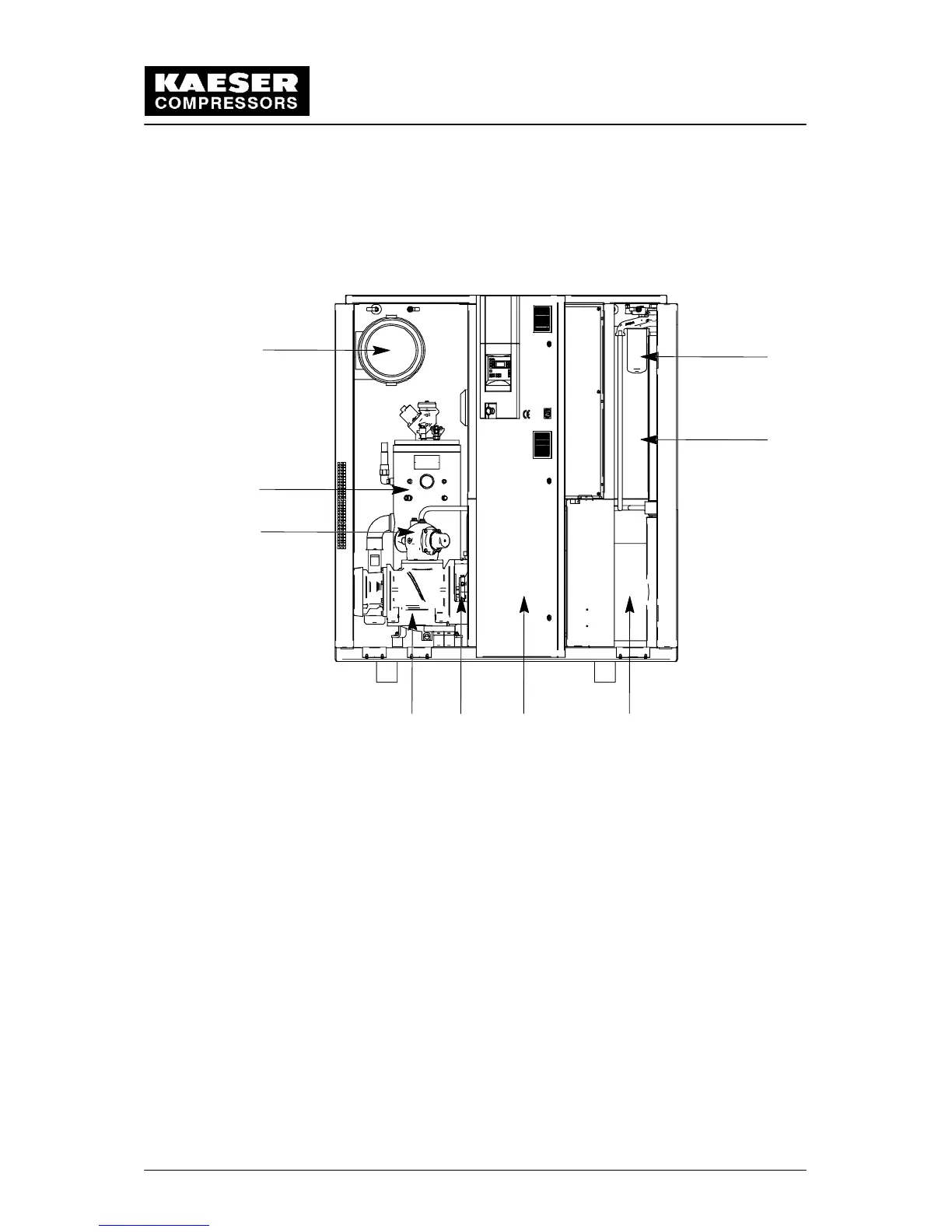
5.3 Identification of the Components
Position details in ( ) correspond with the Pipe and Instrument Flow Diagram
(P & I Diagram)
52 6 3
8
7
1
4
9
1 Inlet valve (2) 6 Control cabinet
2 Coupling (53) 7 Oil separator tank
3 Drive motor (3) 8 Air filter (1)
4 Oil filter (10) 9 Oil/air aftercooler (11/13)
5 Airend (4)
5.4 Pipe and Instrument Flow Diagram (P & I Diagram)
(see following pages)