14 Kamstrup A/S • 5512603_C1_GB_03.2016
MULTICAL® 801
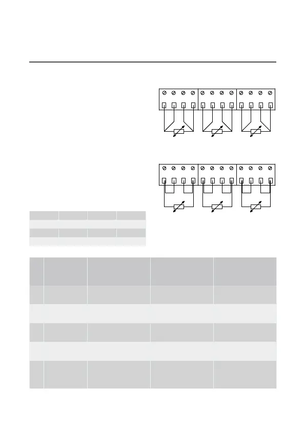
7 Electrical connection
The temperture sensors re
mounted in the terminls of the
clcultor s shown bove. Jumpers
re used when mounting 2-wire
sensors.
In connection with flow sensors
V1 nd V2, the below-mentioned
colours re used for connection of
ULTRAFLOW® nd electronic pick-up
units.
Flow sensors with Reed switch
output must be connected
to terminls 11-10 nd 11-69,
respectively.
V1 V2
- 11 11 Blue
+ 9 9 Red
SIG 10 69 Yellow
4-wire
51 51A 52A 52 3 7 8 4 1 5 6 2
T3 T2 T1
Pt Pt Pt
2-wire
51 51A 52A 52 3 7 8 4 1 5 6 2
T3 T2 T1
Pt Pt Pt
Terminal
No.
Standard
measurement of
heat and cooling
Heat
measurement and
leak surveillance
Energy
measurement
in open systems
T1 1–5–6–2 Sensor in inlet pipe
(red)
Sensor in inlet pipe
(red)
Sensor in inlet pipe
(red)
T2 3–7–8–4 Sensor in outlet
pipe (blue)
Sensor in outlet
pipe (blue)
Sensor in outlet
pipe (blue)
V1 11–9–10 Flow sensor in
inlet or outlet pipe
Flow sensor in
inlet pipe
Flow sensor in
inlet pipe
V2 11–9–69 - Flow sensor in
outlet flow pipe
Flow sensor in
outlet pipe
T3 51–51A–
52A–52
- Tnk/het
exchnger
temperture
Reference sensor
(grey)
Other mkes of flow sensors re usully connected to terminls 10B nd 11B.