15Kamstrup A/S • 5512603_C1_GB_03.2016
MULTICAL® 801
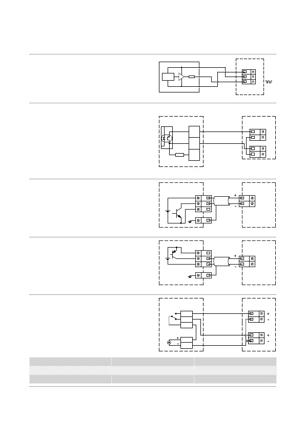
7.1 Examples of connections
The ctive pulse output is direct
connected to the not glvniclly
seprted flow sensor input. This
permits cble length of up to 10 m
between flow sensor nd clcultor.
ULTRAFLOW® 54/34, DN15-125
YELLOW
BLUE
RED
MULTICAL® 801
GND
+3.6 V
10K
Auxiliry voltge from terminls 97A
nd 98A is dded to the pssive
contct output on terminls 10A nd
11A before the signl is connected to
the glvniclly seprted flow sensor
input. This permits cble length of
up to 100 m between flow sensor nd
clcultor.
ULTRAFLOW® 54, DN150-250
6699-903 & 6699-615/6699-624
MULTICAL® 801
10B
11B
97A
98A
56K2
11A
10A
9A
The ctive pulse output of the flow
sensor is connected to the glvniclly
seprted flow sensor input directly.
This permits cble length of up
to 100 m between flow sensor nd
clcultor.
SONOFLO/MAGFLO MkIII MULTICAL® 801
10B (69B)
11B (79B)
V1 (V2)
50
51
52
PE
The ctive pulse output of the flow
sensor is connected to the glvniclly
seprted flow sensor input directly.
This permits cble length of up
to 100 m between flow sensor nd
clcultor.
MAGFLO Mk IV
MULTICAL® 801
56
56
56
56
10B (69B)
11B (79B)
V1 (V2)
The ctive pulse output is direct
connected to the glvniclly
seprted flow sensor input. This
permits cble length of up to 100 m
between flow sensor nd clcultor.
SITRANS F
MAGFLO
MULTICAL® 801
10B
11B
69B
79B
V1
V2
44
45
46
57
58
Heat energy Cooling energy
Sme DΘ polrity E2 = V2 (T1-T2)k E1 = V1 (T1-T2)k
Chnged DΘ polrity E2 = V2 (T1-T2)k E3 = V1 (T2-T1)k