Rev. 1.00
20801-EDEBDA0232-4716-1_EN
14
KBR multicomp F144-NC-1V1C6DO6RO-2 Installation and electrical connection
3.3 Current transformer dimensions
The current transformer is designed based on the current consumption of the
consumers and not the capacitor current. If other measuring devices are con-
nected to a transformer in addition to the reactive power controller, the trans-
former power needs to be dimensioned accordingly. Losses also occur in the
current transformer line that need to be considered if there are large distances
between the transformer and the controller.
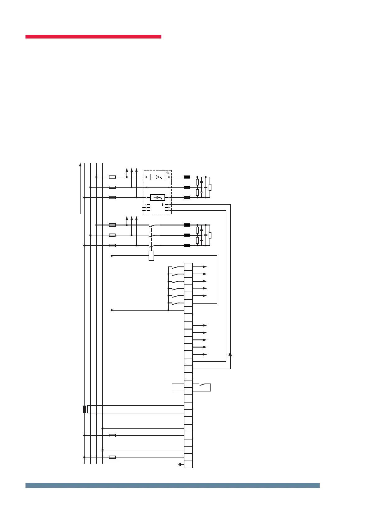
3.4 Standard connection diagram measuring voltage Ph-N
For voltage supply, see nameplate.
L1
EVU
L2
L3
N
Alarm
Steuerspannung/ driving voltage
KL
F1 6A
k6k4k3k2k1 k5
L1 N
85-265V
Hauptstrom/ main current
kl
30....750 V
F2
k12k10k9k8k7 k11
47 48 49 50 51 52 53
Messspannung/ measuring voltage
+24V-
Steuerspannung/
driving voltage <= 250V
+
1 2 10 11
20 21
40
30
41
31
42 43 44 45 46
+
L1 N
PE
Kompensationsanlage
power factor
correction equipment
Kontakt bei
Störung und
im stromlosen
Zustand oen
Contact is open
by no power
and alarm
weitere Stufen
further stages
Verbraucher / consumer
Digitale Ausgänge
digital outputs
Relaisausgänge
relay outputs
Anschlussplan Hybrid PH - N
externe Spannungsquelle
external voltage source

 Loading...


