Rev. 1.00
20801-EDEBDA0232-4716-1_EN
15
KBR multicomp F144-NC-1V1C6DO6RO-2Installation and electrical connection
For voltage supply, see nameplate.
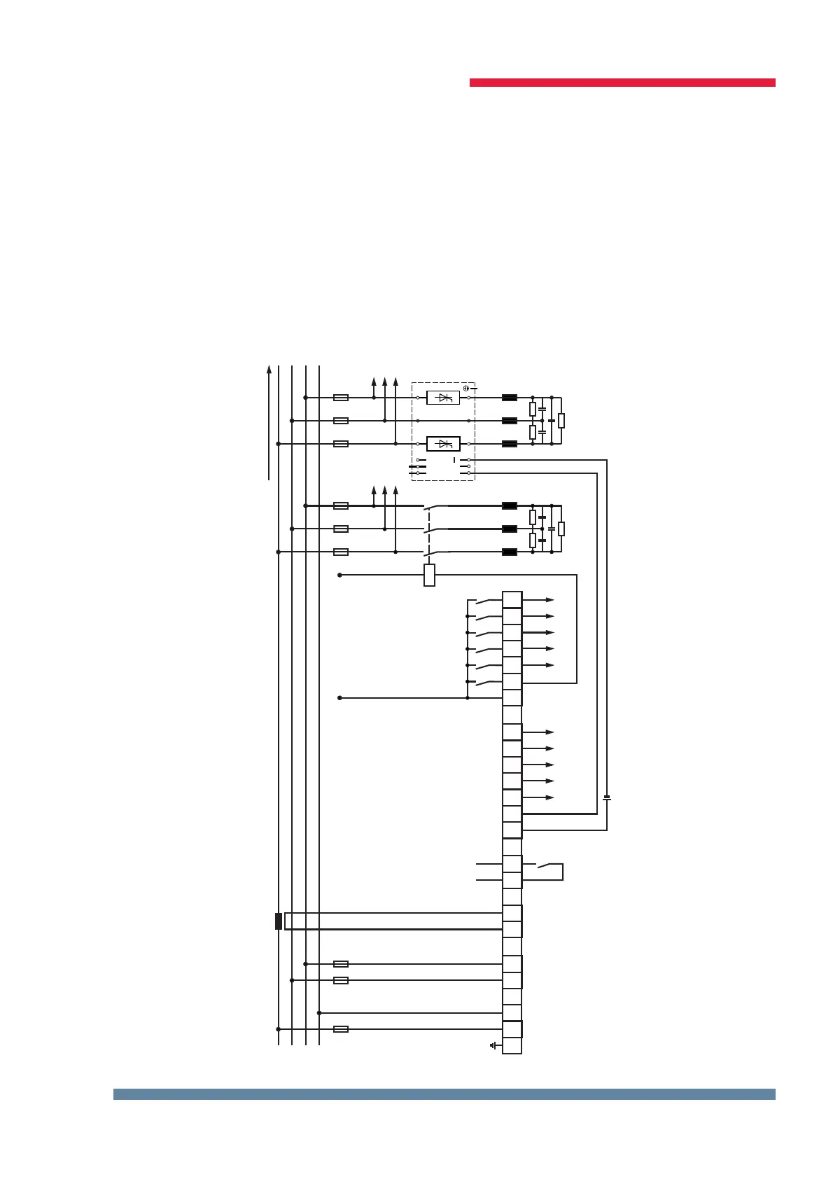
3.5 Standard connection diagram measuring voltage Ph-Ph
L1
EVU
L2
L3
N
Alarm
Steuerspannung/ driving voltage
KL
F1 6A
k6k4k3k2k1 k5
L2 L3
85-265V
Hauptstrom/ main current
kl
30....750 V
F2 F3
k12k10k9k8k7 k11
47 48 49 50 51 52 53
Messspannung/ measuring voltage
+24V-
Steuerspannung/
driving voltage <= 250V
+
1 2 10 11
20 21
40
30
41
31
42 43 44 45 46
+
L1 N
PE
Kompensationsanlage
power factor
correction equipment
Kontakt bei
Störung und
im stromlosen
Zustand oen
Contact is open
by no power
and alarm
weitere Stufen
further stages
Verbraucher / consumer
Digitale Ausgänge
digital outputs
Relaisausgänge
relay outputs
Anschlussplan Hybrid PH - PH
externe Spannungsquelle
external voltage source
 Loading...


