Rev. 1.00
20801-EDEBDA0232-4716-1_EN
42
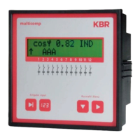
KBR multicomp F144-NC-1V1C6DO6RO-2 Technical data
11.7 Hardware inputs and outputs
11.7.1 Hardware inputs
Voltage
measuring
input
UPH-N or UPH-PH 30 V... 690 V... 790 V AC
Input impedance 750 kOhm
Measuring range 1 measuring range, measuring voltage trans-
former can be programmed
Current
measuring
input
IL1, IL2 or IL3 0.015 A ... 5 A ... 6 A AC
Power consumption approx. 2 VA at 6 A
Measuring range 1 measuring range,
current transformer can be programmed
11.7.2 Hardware outputs
Alarm relay Switching capacity 250 V (AC) / 2 A oating
Capacitor stage
relay
Switching capacity 250 V (AC) / 2 A oating
Optocoupler
output
Switching capacity max. 35 VDC, max. 35 mA, external supply
11.8 Electrical connection
Connection elements Plug terminals
Permissible cross-section
of the connection lines
2.5 mm
2
Measurement
voltage inputs
Fuse protection max. 6 A
Measuring cur-
rent input
Fuse protection NONE!!! Always short-circuit current trans-
former terminals k and l before opening the
circuit!
Input
Control voltage
Fuse protection max. 6 A
Relay output Fuse protection max 2 A medium time-lag
Transformer
connection
Connections see connection diagram

 Loading...