9
ANTRIEBSTECHNIK
6
79
KEB COMBIVERT F4-C
Name: Basis
21.04.99
6
Keep on Running Functions
© KEB Antriebstechnik, 1999
All Rights reserved
Functional Description
Section PageDate Chapter
⇓
⇓
⇓
⇓
⇓
⇓
6.7.4 Electronic Motor
Protection
The motor protective function protects the connected motor against thermal
desctruction caused by high currents. The function corresponds largely to mechanical
motor protective components, additionally the influence of the motor speed on the
cooling of the motor is taken into consideration. The load of the motor is calculated
from the measured apparent current (ru.9) and the adjusted rated motor current
(dr.2).
For motors with separately driven fan or at rated frequency of a self-ventilated motor
following tripping times (VDE 0660, Part 104) apply:
1,2 • I
n
⇒ 2 hours
1,5 • I
n
⇒ 2 minutes
2 • I
n
⇒ 1 minute
8 • I
n
⇒ 5 seconds
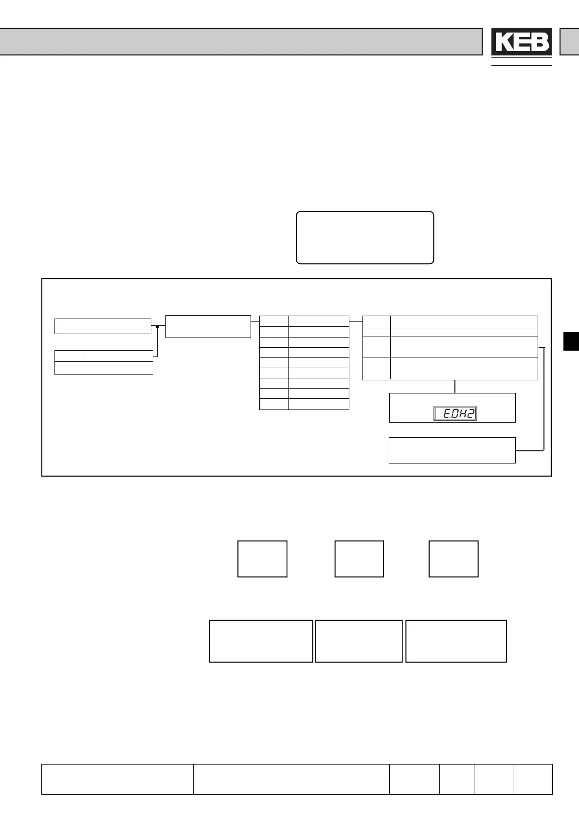
Pn.3 Electronic motor protection
0 no function
1 only warning, motor with separate fan
2 only warning, motor without separate fan
3 motor with separate fan (error E.OH2)
4 motor without separate fan (error E.OH2)
ru.9 Apparent current
dr.2 Rated motor current
0.1…460.0 A
s. Chap. 6.3 „Digital Outputs“
do.1...do.4 „Value7“
Pn.15 Counter select.
0 Counter 0
1 Counter 1
2 Counter 2
3 Counter 3
4 Counter 4
5 Counter 5
6 Counter 6
7 Counter 7
Parameter set selection
see Chap. 6.8
Hardware error detection
Picture 6.7.4.a Principle of electronic motor protective function
If several motors are operated with one inverter, each motor can be protected
individually by selecting different counters (0...7).
Example:- a different counter is assigned to each motor
1. Motor 2. Motor 3. Motor
⇓⇓⇓
Counter 0 Counter 1 Counter 2
- this counter is now adjusted in all parameter sets of the corresponding
motor
Counter 0=Value „0“ Counter 1=Value„1“ Counter 2=Value „2“
Set 1 Set 5 Set 0 Set 2 Set 6 Set 3
Enter motor data in the
corres-ponding parameter
sets!
Counter Selection Pn.15
⇓
⇓
⇓
⇓
Adjust ⇓⇓ ⇓
following 0.Pn.15 = 0 2.Pn.15 = 1 3.Pn.15 = 2
values: 1.Pn.15 = 0 6.Pn.15 = 2
5.Pn.15 = 0
The counter works only in the active set with the measured value. In all sets that are
not active it is counted down. If one counter exceeds the limit, a warning in dependence
on Pn.3 is given (do.1...do.4 Value „7“) or the inverter switches off with error E.OH2.
 Loading...


