6 10
KEB COMBIVERT F4-C
8
Name: Basis
19.11.98
Chapter Section Page Date
© KEB Antriebstechnik, 1997
All Rights reserved
Functional Description Encoder Interface
6.10.7 Evaluation of
Incremental
Encoders
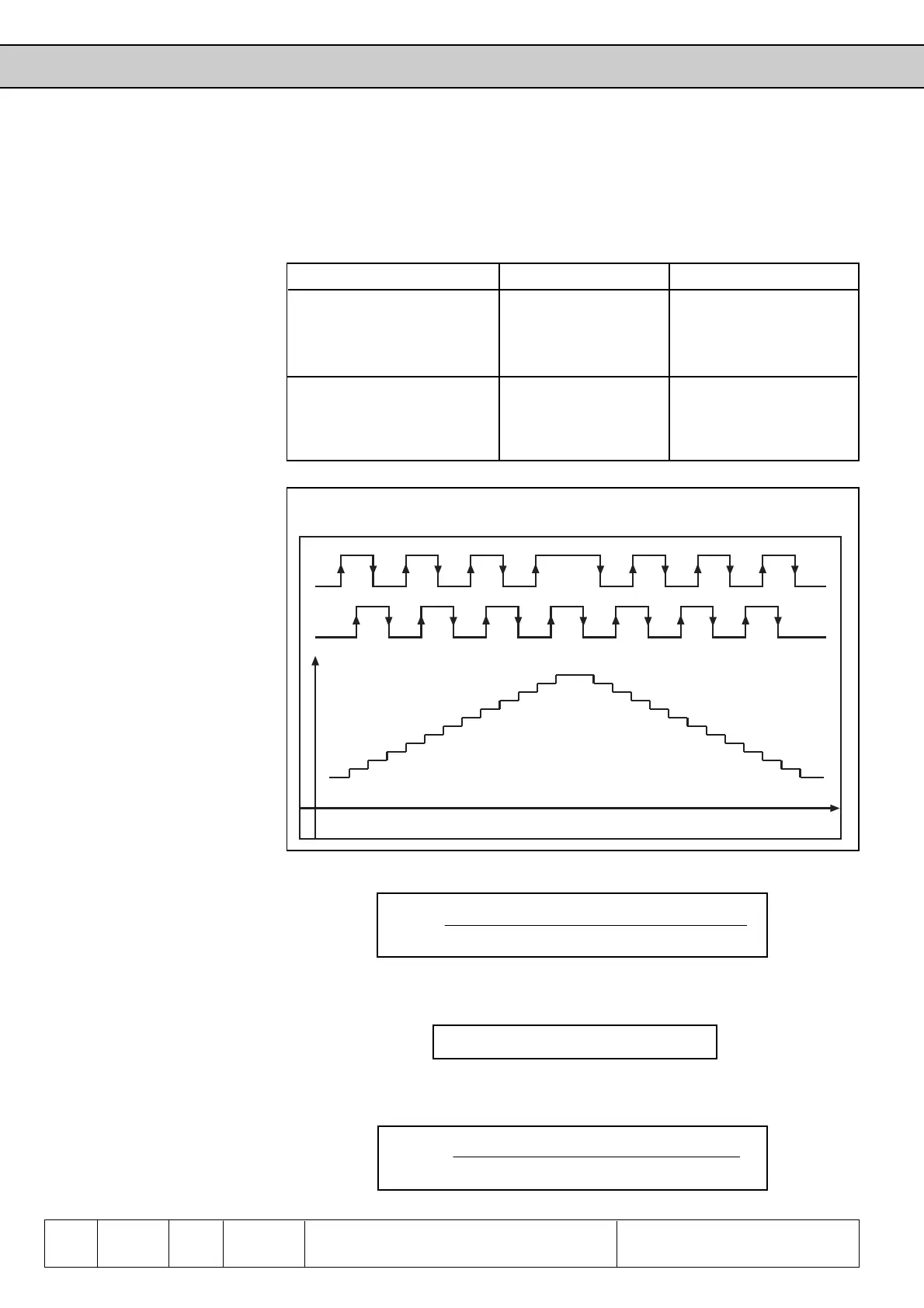
The evaluation of the incremental encoders is supported by two signals set off by 90°
and signal levels according to RS422-standard (refer to ‘Technical Data‘). Basically
the incremental encoder evaluation consists of a counter which is increased or
decreased under following conditions.
Changing counter content: Signal A Signal B
Increase of counter Pos. edge State Low
State High Pos. edge
Neg. edge State High
State Low Neg. edge
Decrease of counter Pos. edge State High
State Low Pos. edge
Neg. edge State Low
State High Neg. edge
Fig. 6.10.7.a Evaluation of incremental encoder signals
The speed and the direction of rotation can now be calculated from the counter change
per time:
The encoder line number is adjusted via dr.25 (channel 1) or dr.30 (channel 2). The
time gate can be adjusted via dr.37 (channel 1) or dr.38 (channel 2) according to
following formula:
Thus the resolution of the incremental encoder evaluation depends on the line number
of the used encoder and the size of the time gate for the differentiation of the counter
content.
A
B
INC
time
n =
counter difference
4 • encoder increments • time gate
time gate = 4ms • 2
dr.37
∆
n
=
1
4 • encoder increments • time gate
 Loading...


