6 10
KEB COMBIVERT F4-C
6
Name: Basis
19.11.98
Chapter Section Page Date
© KEB Antriebstechnik, 1997
All Rights reserved
Functional Description Encoder Interface
3 2 1
1 2 3
123
P1
123
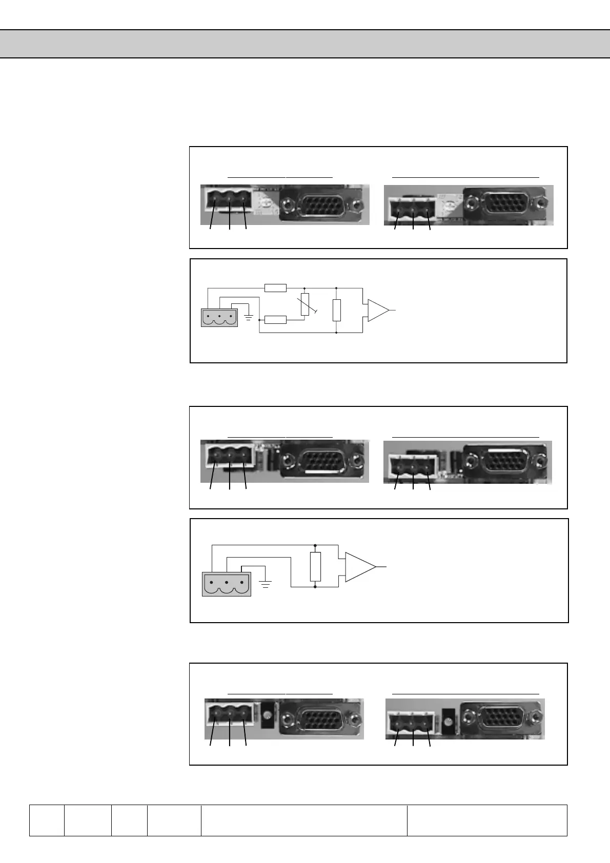
6.10.3 Encoder Interface
with Tacho Gene-
rator evaluation
Fig. 6.10.3.a Incremental encoder interface with tacho generator evaluation
Housing size D and E From housing size G upwards
The incremental encoder Interface of the following option is identical with channel 1
of 6.10.2.
Channel 1 (X4) Channel 1 (X4)
Fig. 6.10.3.b Block diagram of tacho evaluation
R
i
: 50...55kΩ (depends on P1)
U
Tacho
: max. ±100V
Terminal 1: Tacho +
Terminal 2: Tacho -
Terminal 3: PE
6.10.4 Encoder Interface
with ±10V Input
3 2 1
1 2 3
Fig. 6.10.4.a Incremental encoder interface with ±10V input
Housing size D and E From housing size G upwards
The incremental encoder Interface of the following option is identical with channel 1
of 6.10.2.
Channel 1 (X4) Channel 1 (X4)
Fig. 6.10.4.b Block diagram of ±10V input
R
i
: 60kΩ
U
Tacho
: max. ±10V
Terminal 1: Analog option +
Terminal 2: Analog option -
Terminal 3: PE
6.10.5 Encoder Interface
with Initiator Input
3 2 1
1 2 3
Fig. 6.10.4.a Incremental encoder interface with initiator input
Housing size D and E From housing size G upwards
The incremental encoder Interface of the following option is identical with channel 1
of 6.10.2.
Channel 1 (X4) Channel 1 (X4)

 Loading...


