7
ANTRIEBSTECHNIK
6
27
KEB COMBIVERT F4-C
Name: Basis
6
22.03.01
Section
Page
Date
© KEB Antriebstechnik, 1999
All Rights reserved
Chapter
Functional DescriptionAnalog In- and Outputs
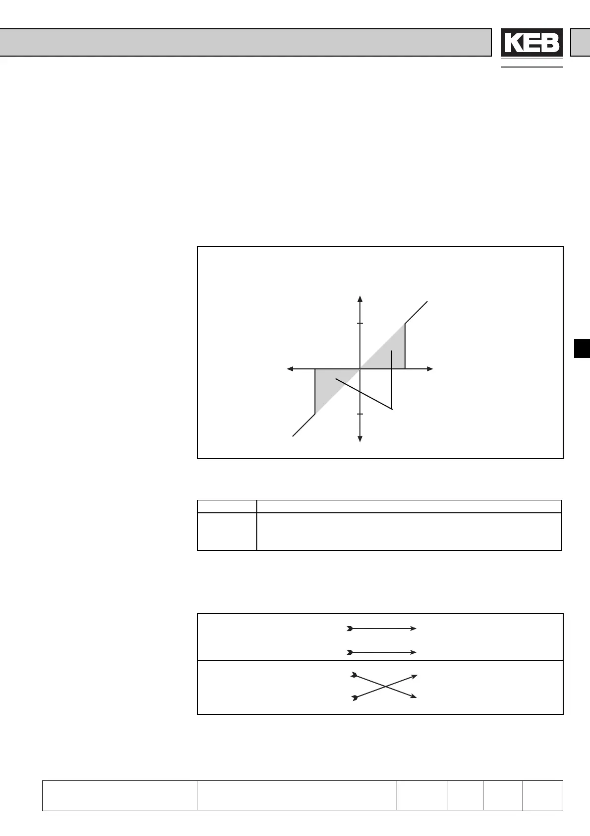
-10%
10%
10%
-10%
An.12 = 0
An.12 = 1
6.2.6 Zero Clamp Speed
(An.2 /An.8 /
An.27)
With capacitive and inductive interferences on the input lines or voltage fluctuations
of the signal source, it is possible that the motor, connected to the inverter, trembles
at a standstill in spite of analog input filter. To suppress this is the assignment of the
zero clamp speed.
With the parameters An.2, An.8, and An.27 the respective analog signals at the
output of the characteristics amplifier can be faded out in an area between 0...10%.
The adjusted value is valid for both rotation directions.
If a negative percentage is adjusted, the hysteresis acts additional to the zero point
even around the actual setpoint value. Setpoint value changes at constant operation
are taken over, when the value is larger than the adjusted hysteresis.
from the characteristic
amplifier
for further signal processing
fade out range
Input Parameter Value Range Resolution Standard Value
±REF An.2
REF An.8 -10...10% 0,1% 0,2%
Option An.27
6.2.7 Selection Set-
point Value/ Aux
Input (An.12)
The control includes internally two analog channels (REF-internal and AUX-internal).
With „parameter“ An.12 the two external analog inputs ±REF and REF can be assigned
alternatively to both of the internal analog channels.
±REF REF-internal
REF AUX-internal
±REF REF-internal
REF AUX-internal
6.2.8 Simulate Analog
Option with ±REF
(An.22 Bit 6)
In order to activate this function set bit 6 (value 64) of parameter An.22 (see chapter
6.2.4 at the bottom of page 5). When this bit is set, the analog setpoint value from
±REF is fed simultaneously into the option channel. You can find the further signal
processing of the option channel at the encoder interface.
6.2.6 Zero clamp speed
Range of Values

 Loading...


