Page 7.6 - 4 COMBIVERT F5-A, -E, -H © KEB, 2012-10
Motor data and controller adjustments of the synchronous motor
dr.26 = EMK
eff
x √ 2
No decimal places can be entered in parameter dr.26 for the EMC. The voltage per 1000 rpm at high-frequency
motors is partly very low, that an integer setting falsies the EMC value. Parameter dr.63 (DSM EMC HR) can
be used for higher accuracy.
In order that there is a downward compatibility to older parameter lists, the parameter can be deactivated with
value "0: off".
The maximum permissible speed which is displayed in ru.79 (abs. speed [EMC]) is also calculated from the
EMC. The maximum DC link voltage, UZKmax, can be found in the power circuit manual.
Max. UDC
link
x 1000 rpm
—————————
dr.26
ru.79 =
DSM stand still current (dr.28)
The standstill continuous current affects the electronic motor protection function (see chapter 7.13.).
7.6.1.2 Controllerconguration
Parameter cS.00 must set to value 4: "speed control" for closed-loop operation.
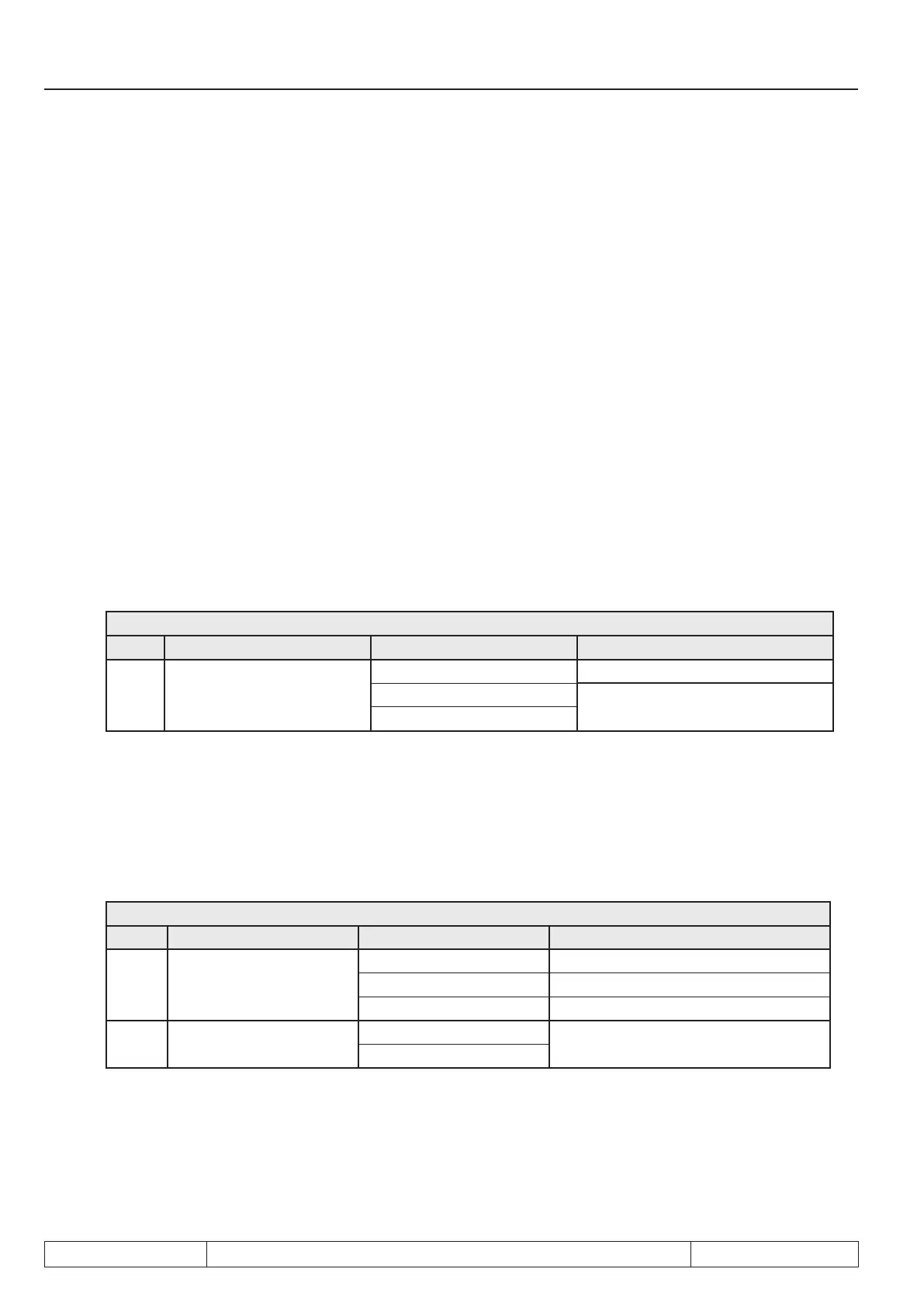
cS.00Controllerconguration
Bit Description Value Function
0...3 Control mode
4: Speed control
5: Torque control
(description see chapter 7.7)
6: Torque/ speed
7.6.1.3 Actual value source
The actual value source for speed control must be selected in parameter cS.01 .
Possible values for drives with speed encoder are 0 (speed measurement via encoder interface channel 1) or
1 (speed measurement via encoder interface channel 2).
Description of the correct parameter setting of the encoder interfaces is made in chapter 7.11 "Speed measure-
ment". cS.01 = 2 (calculated actual value) must be selected at operation without speed encoder (only SCL).
cS.01 Actual value source
Bit Description Value Function
0...1 Actual value source
0: Channel 1 Control to encoder interface 1
1: Channel 2 Control to encoder interface 2
2: calculated actual value Control to estimated speed
2 System inversion
0: off
4: An
With activation of the system inversion it is reached that the motor with selected rotation direction "forward"
(e.g. by setpoint- or rotation setting) has the physically direction "reverse" respectively at setting "reverse" the
physical rotation "forward". Precondition is a correct wiring of motor and speed feedback (if available).
 Loading...


