7.12.3.3 Synchronous mode / position normalisation
The channel where the slave receives the master position is selected via parameter PS.01 actual position sour-
ce. This must be encoder channel 2 for most applications. (Off-the-shelf cables and a terminating resistor that
can be switched off exist only for channel 2 ).
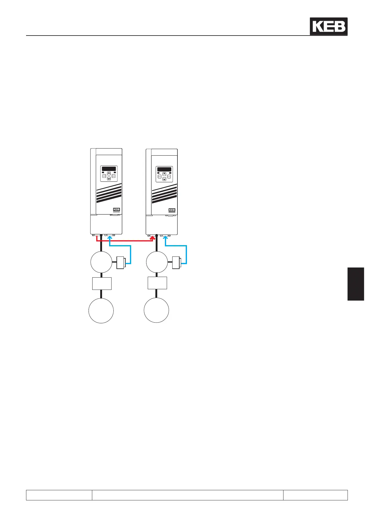
Figure 7.12.3.4 Position normalisation
START
STOP
FUNC.
SPEED
ENTER
F/R
ANTRIEBSTECHNI K
START
STOP
FUNC.
SPEED
ENTER
F/R
ANTRIEBSTECHNI K
X3B X3A X3B X3A
3
~
3
~
Load
i= 5,25
Load
i= 15
speed
closed-loop
master drive
speed
closed-loop
slave drive
forward direc-
tion of rotation
reverse direc-
tion of rotation
The adjoining gure shows a typical
synchronous application.
If the load of the master drive
has travelled one revolution, the load of
the slave should also have travelled one
revolution (in the opposite direction).
This is the case for e.g. printing ma-
chines or
rolling machines.
The slave position (i.e. the number of increments of the slave motor) is displayed in parameter ru.54 "actual
position". In ru.54, one revolution of the slave load corresponds to:
ec.01 "encoder 1 (inc/r)" x gear factor slave
The master position is displayed in parameter ru.56 "set position". The display occurs in increments and is con-
verted to the slave position. The conversion considers the ratio of the increments per revolution of the encoder
and the ratio of the two gear factors. If the master is connected to encoder channel 2, the gear factor of the
slave must be entered in parameter Ec.14 "gear factor 2 numerator" and the gear factor of the master must be
entered in parameter Ec.15 "gear factor 2 denominator" for conversion of the gear ratios.
Since only integer values can be preset, the gear factors must be extended correspondingly
(15 : 5.25 becomes 1500 : 525). Display in ru.56 (master position converted to slave units):
Posi- and synchronous operating
© KEB, 2012-10 COMBIVERT F5-A, -E, -H Page 7.12 - 17
7
 Loading...


