Posi- and synchronous operating
© KEB, 2012-10 COMBIVERT F5-A, -E, -H Page 7.12 - 7
7
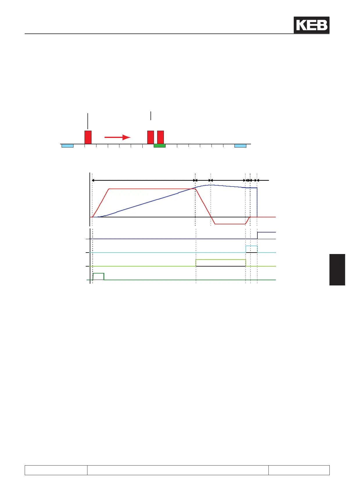
The following two pictures show an exemplary approach to reference point process. The further possibililties
programmable in PS.14 are shown later in this chapter.
1000 2000 3000 4000 5000 6000 7000 80000
5/6 2/3
Start
point search
completed
1
PS.21: Approach to
reference point Speed =
positive
Reference
point switch
Limit switch left Limit switch
right
1 2 3 4 5 6
Start approach
to reference
point
Reference point
switch
Target window
reached
Approach to
reference point
completed
ru.54: actual
position
ru.02: Set
speed
1. PS.21 = positive, i.e., the drive accelerates with the ramp from PS.20 and seeks in forward direction for
the reference switch
2. Stopping at the reference switch
3. Free driving of the reference switch with free drive-speed (PS.21 / PS.22)
4. Stopping of the drive with ramp from PS.20
Setting of the signal "target window reached"
5. Wait for the damping period of 100ms
6. Overwriting the current actual position (ru.54) with the reference point position (PS.17)
Resetting of the signal "target window reached"
Setting of the signal "approach to reference point completed"
Stopping of the drive left to the reference point (programmable via PS.14)
 Loading...


