Protective functions
© KEB, 2012-10 COMBIVERT F5-A, -E, -H Page 7.13 - 25
7
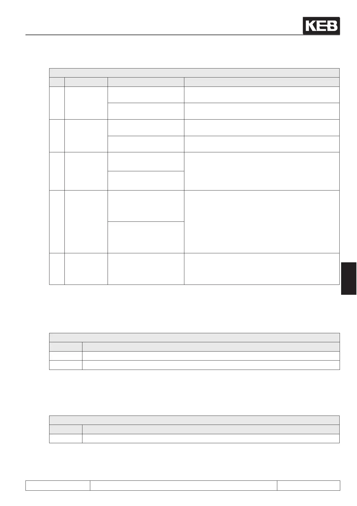
Pn.19: Stall mode
Bit Meaning Value Explanation
4
Release of
the function
0: only at constant run
Stall function only active at constant run (see inverter
state)
16: always (also during the
ramp)
Stall function always active
5 Variable
0: Apparent current
The stall function intervenes if the apparent current
(ru.15) exceeds the stall level Pn.20.
32: Active current
The stall function intervenes if the amount of the active
current (ru.17) exceeds the stall level Pn.20.
6
Control direc-
tion
0: Deceleration
Fits the function to the torque / speed characteristic of
the application.
Examples: For a fan, one must decelerate if the current
level is exceeded. For drilling machines, one must acce-
lerate.
64: Acceleration
7
Level decre-
ase above
rated frequen-
cy
0: no
Determines whether the current limit that activates the
stall function should be decreased above the rated point.
The decrease is then done according to the following
formula:
(
Rated point (uf.00)
−−−−−−−‒−−−−−−−−
Actual frequency
(ru.03)
)
2
Current limit = Pn.20
128: yes
8
Constant
current limit
release
256 Constant current limit always released
Stall level (Pn.20)
The stall level is adjusted in parameter Pn.20. When exceeding this limit, the inverter increases or decreases
automatically the output frequency (depending on the adjustment in Pn.19) in order to reduce the load.
Pn.20: Stall level
Value Explanation
0...199 % Current limit in % (reference value: 100% = rated current of the FI (In.01))
200: off Stall function deactivated
Stall acc/dec time (Pn.21)
The rate of change of the output frequency is dependent on Pn.21. Depending on the setting of Pn.19, the ramp
time of the stall function or the time constant of the controller is adjusted here.
Pn.21: Stall acceleration/deceleration time
Value Explanation
0...300s Ramp time and time constant of the controller, respectively
 Loading...


