Operating and appliance data
© KEB, 2012-10 COMBIVERT F5-A, -E, -H Page 7.1 - 7
7
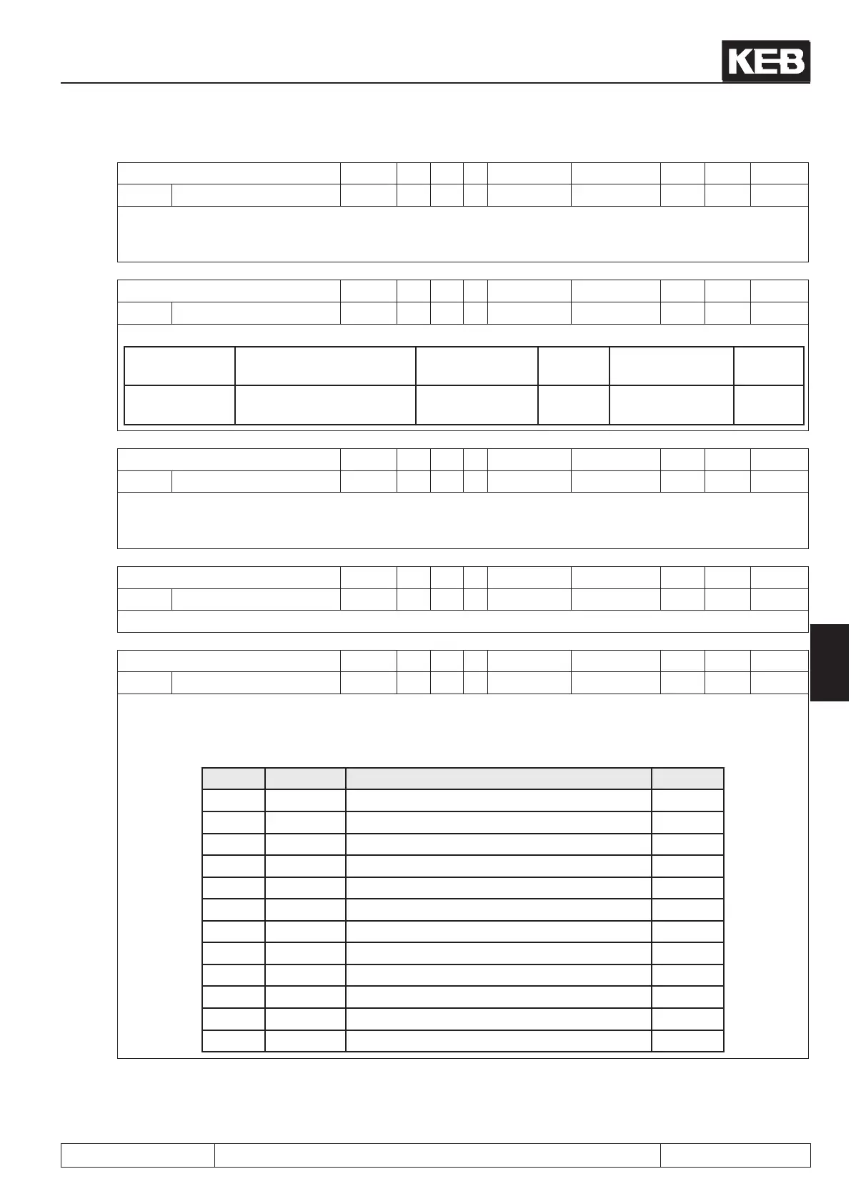
Parameter Addr. R PG E Min. value Max. value Res. [?] Default
ru.17 active current 0211h RO - - -3276.7 3276.7 0.1 A -
Display of the torque-forming active current. Negative current corresponds to generatoric operation, positive
current corresponds to motoric operation. The more precise the motor data are entered, the more precise is
the indication of the active current. The maximum values depend on the size of the inverter.
Parameter Addr. R PG E Min. value Max. value Res. [?] Default
ru.18 actual DC voltage 0212h RO - - 0 1000 1 V -
Display of current DC-link voltage. Typical values:
Normal opera-
tion:
230V-class approx. 300-
330V
Overvoltage
(E.OP):
approx.
400 V
Undervoltage
(E.UP):
approx.
216 V
400V-class approx. 530-
620V
approx.
800 V
approx.
240 V
Parameter Addr. R PG E Min. value Max. value Res. [?] Default
ru.19 peak DC voltage 0213h RO - - 0 1000 1 V -
ru.19 permits the detection of short-time voltage rises within an operating cycle. The highest value of ru.18 is
stored in ru.19. The peak value memory can be deleted by pressing the keys UP, DOWN or ENTER and by bus
through writing any chosen value to the address of ru.19. The switch off of the inverter also clears the memory.
Parameter Addr. R PG E Min. value Max. value Res. [?] Default
ru.20 output voltage 0214h RO - - 0 1000 1 V -
Display of the current output voltage.
Parameter Addr. R PG E Min. value Max. value Res. [?] Default
ru.21 Terminal Status 0215h RO - - 0 4095 1 - -
Display of the digital inputs controlled currently. The logic levels are indicated at the input terminals or at the
internal inputs regardless of the following logic operations (also see chapt. 7.3 „Digital inputs“). According to
following table a specic decimal value is given out for each digital input. If several inputs are controlled, the
sum of the decimal values is indicated.
Bit -No. Dec. Input Terminal
0 1 ST (prog. input „control release/reset“) X2A.16
1 2 RST (prog. input „reset“) X2A.17
2 4 F (prog. input „forward“) X2A.14
3 8 R (prog. input „reverse“) X2A.15
4 16 I1 (prog. input 1) X2A.10
5 32 I2 (prog. input 2) X2A.11
6 64 I3 (prog. input 3) X2A.12
7 128 I4 (prog. input 4) X2A.13
8 256 IA (internal input A) no
9 512 IB (internal input B) no
10 1024 IC (internal input C) no
11 2048 ID (internal input D) no
 Loading...


