Page 7.1 - 18 COMBIVERT F5-A, -E, -H © KEB, 2012-10
Operating and appliance data
Parameter Addr. R PG E Min. value Max. value Res. [?] Default
In.
17
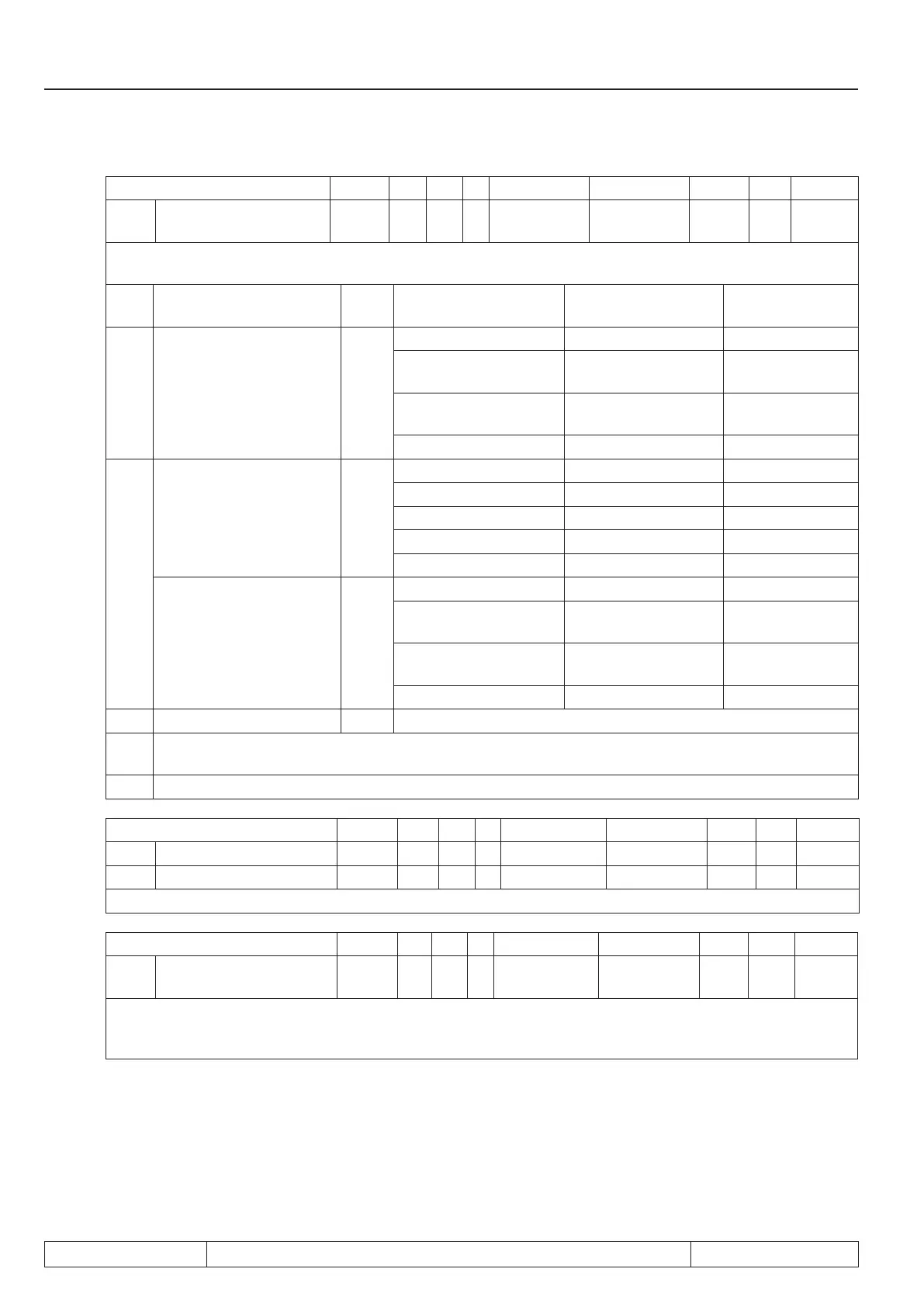
Temperature mode 0E11h RO - - 0 LTK 1 - LTK
Parameter In.17 displays in high byte the temperature mode of the inverter. The desired function is adjusted
with Pn.72 and operates in accordance with the following table:
In.
17
Function of T1, T2 Pn.72 Resistance Display ru.46 Error/ warning
1)
0xh
PTC
(in accordance with DIN
EN 60947-8)
-
< 750 Ω T1-T2 closed
-
0.75…1.65 kΩ
(reset resistance)
not defined
-
1.65…4 kΩ
(tripping resistance)
not defined
x
> 4 kΩ T1-T2 open
x
5xh
KTY84 (standard) 0
< 215 Ω
Detection error x
498 Ω 1°C
-
2)
1 kΩ 100°C
x
2)
1,722 kΩ 200°C
x
2)
> 1811 Ω
Detection error 254 x
PTC
(in accordance with DIN
EN 60947-8)
1
< 750 Ω T1-T2 closed
-
0.75…1.65 kΩ
(reset resistance)
T1-T2 closed
-
1.65…4 kΩ
(tripping resistance)
T1-T2 open
x
> 4 kΩ T1-T2 open
x
6xh PT100 - on inquiry
1)
The column is valid at factory setting and Ud.02 ≥ 4 (F5-Multi, Servo). At Ud.02 < 4 (F5-General) the
function must be programmed accordingly with parameters Pn.12, Pn.13, Pn.62 and Pn.72.
2)
The disconnection is depending on the adjusted temperature in Pn.62.
Parameter Addr. R PG E Min. value Max. value Res. [?] Default
In.22 User parameter 1 0E16h RW - - 0 65535 1 - 0
In.23 User parameter 1 0E17h RW - - 0 65535 1 - 0
This parameters are not assigned to any function and are available to the user for input.
Parameter Addr. R PG E Min. value Max. value Res. [?] Default
In.
24
Last error 0E18h R - - 0 255 1 - -
In.24 stores the 8 errors that occurred last. The display is set-programmable. E. UP is not stored. The error
messages are described in chapter 8. If the value 0 is written, (only possible with supervisor password), all
error messages in all sets are deleted.
 Loading...


