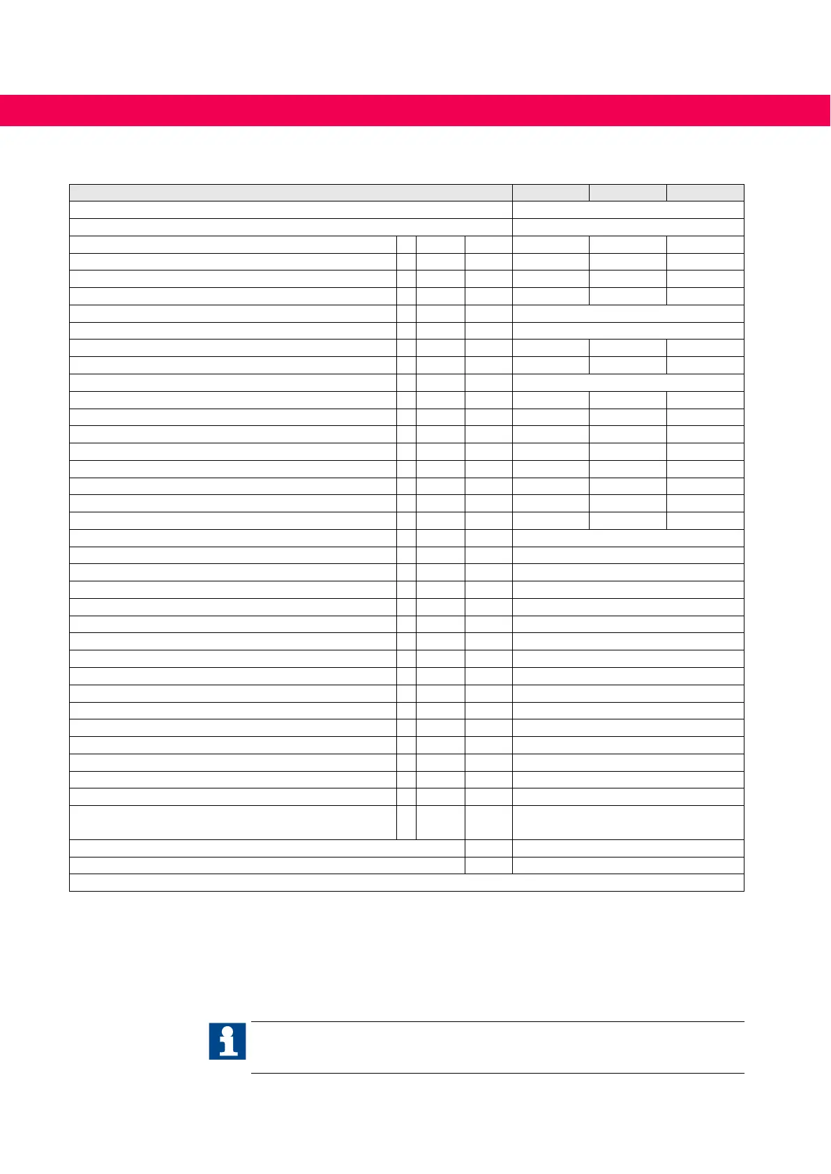
3.3 Technical data G6 400V class
Inverter size 07 09 10
Housing size A
Phases 3
Output rated power S
out kVA 1.8 2.8 4.0
Max. rated motor power P
mot kW 0.75 1.5 2.2
Output rated current I
N A 2.6 4.1 5.8
Output rated current UL I
NUL A 1.8 3.4 4.8
Short time current limit 1) I
HSR % 180
Over current 1) I
OC % 216
Maximum current at 0Hz / Corner frequency fd at fS=4 kHz
1) If0/Ifd % 100 / 180 100 / 180 100 / 180
Maximum current at 0Hz / Corner frequency fd at fS=8 kHz
1) If0/Ifd % 100 / 180 100 / 150 85 / 150
Corner frequency f
d Hz 6
Input rated current I
in A AC 3.6 6.0 8.0
Input rated current (UL) I
inUL A AC 2.5 4.8 7.0
Input rated current DC 2) I
indc A DC 1.9 3.7 5.2
Input rated current DC (UL) 2) I
indcUL A DC 1.6 3.0 4.2
Max. permissible main fuse type gG A 16 16 16
Rated switching frequency 3) f
SN kHz 8 4 4
Max. switching frequency 3) f
Smax kHz 8 8 8
Power dissipation at nominal operating 4) P
D W 45 49 70
Power dissipation standby (no control release) 4) P
Dnop W 10
Max. heat sink temperature T
HS °C 90
Temperature for derating the switching frequency 5) T
dr °C 85
Temperature for uprating the switching frequency 5) T
ur °C 80
Min. braking resistor R
Bmin Ω 120
Max. braking current I
Bmax A 7
Input rated voltage U
N V AC 400 (UL: 480)
Input voltage range U
in V AC 340…528 ±0
Mains frequency f
N Hz 50 / 60 ±2
Rated input voltage DC U
Ndc V DC 565 (UL: 680)
Input voltage range at DC supply U
indc V DC 480…746 ±0
DC switch-off level „Error! Underpotential“
UUP V DC 240
DC switch-off level braking resistor
UB V DC 780
DC switch-off level „Error! Overpotential“
UOP V DC 840
Output voltage 6) U
A V 3 x 0…Uin
Output voltage at DC devices 6) UA V 3 x 0…Uindc/√2
Output frequency (depending on the control mode) 3) f
out Hz
0…400 (fs=4 kHz)
0…599 (fs=8 kHz)
Minimum waiting period between two switch-on procedures min 5
Insulating resistance (500 V DC)
MΩ 10
Table 8: Technical data 400V class
1) The values refer percentage to the output rated current IN.
2) The values resulting from rated operation with B6 rectier circuit and mains choke 4% UK.
3) The output frequency is to be limited in such a way that it does not exceed 1/10 of the switching frequency.
4) Rated operation corresponds to U
N = 400 V; fSN; fA = 50 Hz (typically value).
5) On reaching the temperature Tdr the switching frequency is step down. The switching frequency is increased again on cooling down
to temperature Tur.
6) The voltage at the motor is dependent on the series-connected units and on the control method
, see „Calculation of the motor voltage“.
The technical data are for 2/4-pole standard motors. With other pole numbers the drive
converter must be dimensioned onto the motor rated current. Contact KEB for special
or medium frequency motors.
28
TECHNICAL DATA G6 400V CLASS

 Loading...


