4.2.5 Connection of a braking resistor
4.2.5.1 Terminal strip X1B connection braking resistor
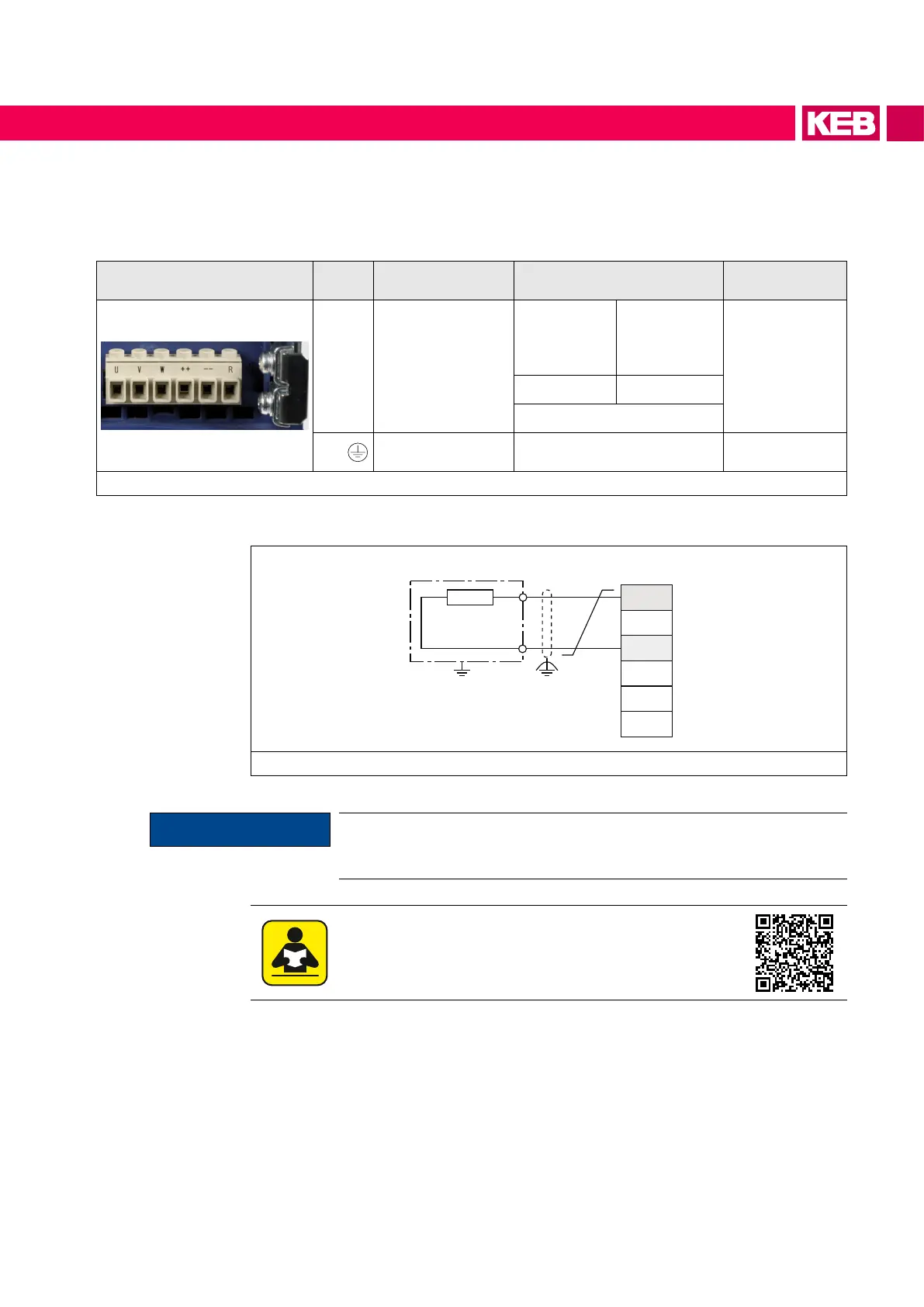
X1B Name Function Cross-section
Tightening
torque
++, R
Connection for
braking resistor
(alternatively ++,
PB)
AWG
without
wire-end
ferrule
mm²
with
wire-end
ferrule
0.5…0.6 A
5…6 lb-inch
24...14 0.25...2.5
Stranded wire
PE,
Connection for
protective earth
Screw M4
for ring cable lug
1.3 Nm
11 lb inch
Figure 15: Terminal strip X1B connection of a braking resistor
4.2.5.2 Wiring of an intrinsically safe braking resistor
X1B
R
- -
++
U
V
W
R
PA
Figure 16: Wiring of an intrinsically safe braking resistor
ATTENTION
Only "intrinsically safe" braking resistors are permissible for this oper-
ation, since these resistors interrupt themselves at fault such as safety
fusewithoutrerisk.
Technical data and design for intrinsically safe braking re-
sistors.
www.keb.de/fileadmin/media/Manuals/dr/ma_dr_safe-braking-resis-
tors-20106652_en.pdf
41
CONNECTION OF THE POWER UNIT

 Loading...


