ATTENTION
Protect motor against voltage peaks !
Driveconvertersswitchattheoutputwithdu/dt≤5kV/µs.
Voltage peaks
that endanger the insulation system at the motor can occur especially
in case of long motor cables (> 15 m).
Amotorchoke,adv/dt-lterorsine-waveltercanbeusedforprotec-
tion of the motor.
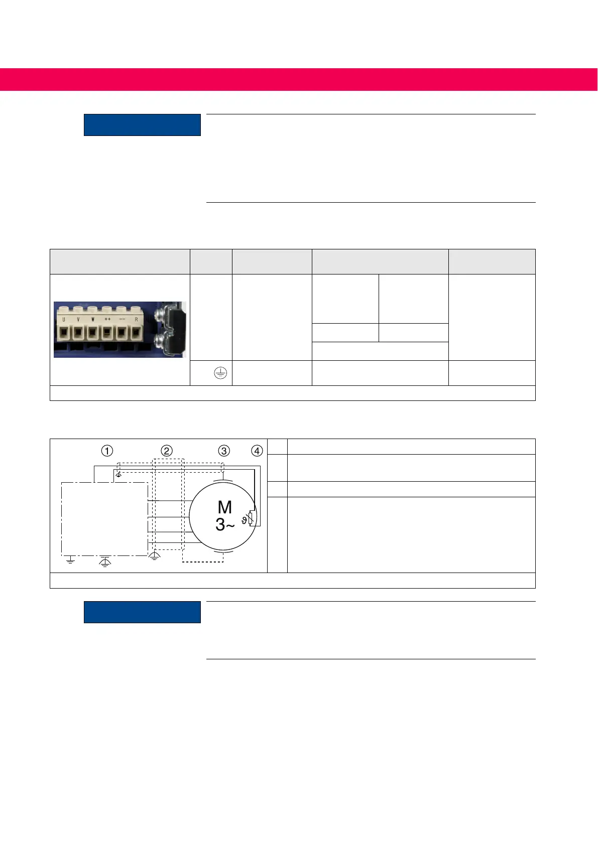
4.2.4.7 Terminal strip X1B motor connection
X1B Name Function Cross-section
Tightening
torque
U, V, W Motor connection
AWG
without
wire-end
ferrule
mm²
with
wire-end
ferrule
0.5…0.6 A
5…6 lb-inch
24...14 0,25...2,5
Stranded wire
PE,
Connection for
protective earth
Screw M4
for ring cable lug
1.3 Nm
11 lb inch
Figure 13: Terminal strip X1B motor connection
4.2.4.8 Wiring of the motor
L1
L2
L3
U
V
W
PE
U
V
W
PE
PE
T1 T2
1 KEB COMBIVERT
2 Apply motor cable, shielding on both sides over a
large surface on the function earth
3 Three-phase motor
4
Temperature monitoring (optional)
see „Connection of a temperature detection“
Figure 14: Wiring of the motor
ATTENTION
• Do not lay PTC cable of the motor (also shielded) together with con-
trol cable !
• PTC cable inside the motor cable only permissible with an addition-
ally shielding (double shielding) !
40
CONNECTION OF THE POWER UNIT

 Loading...


