3.5.1 Control cabinet installation
The power dissipation for the control cabinet dimension is to be taken from the technical
data.
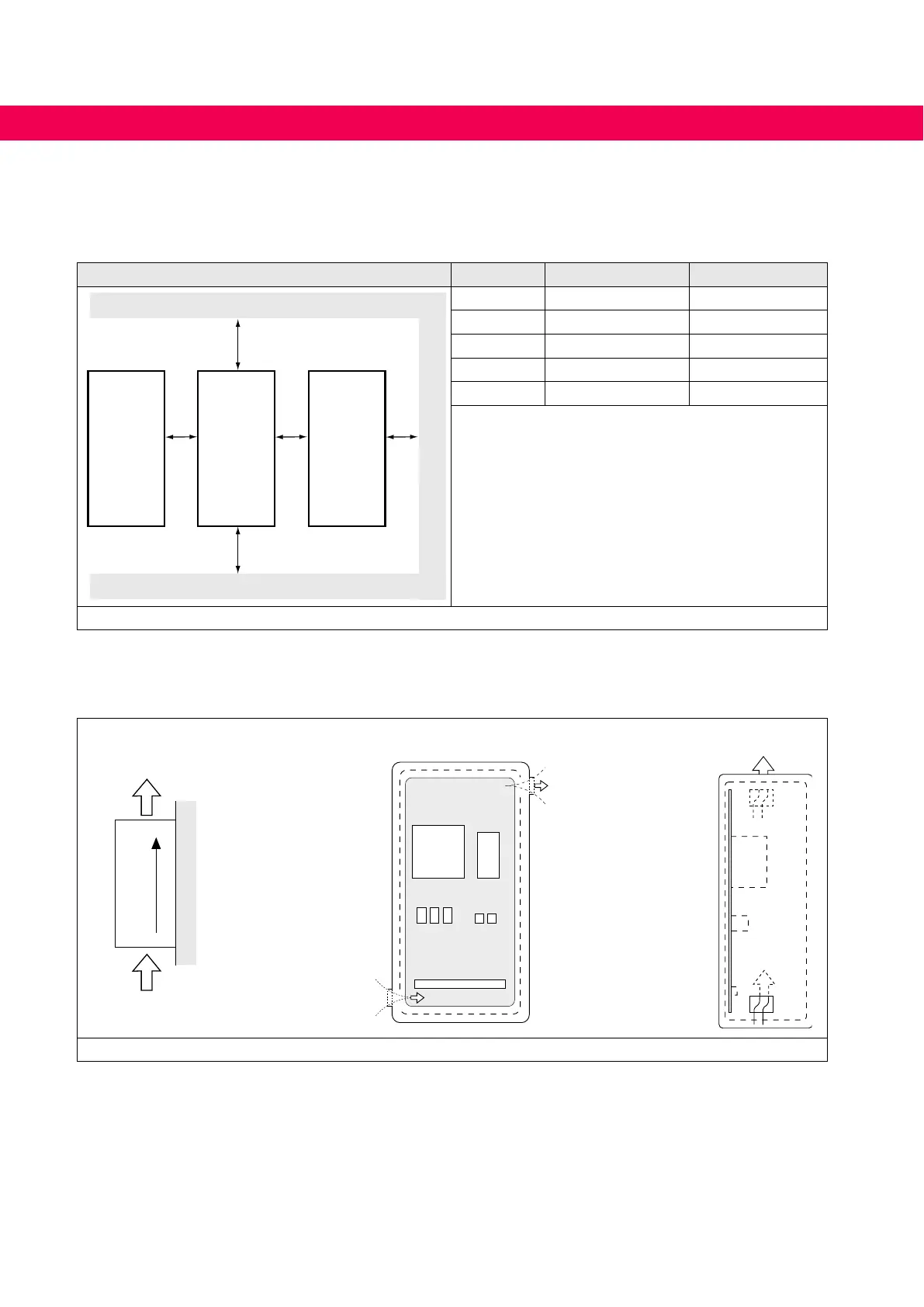
Mounting distances Dimension Distance in mm Distance in inch
C
A
B
DD
A 150 6
B 100 4
C 30 1.2
D 0 0
X
1)
50 2
1) Distance to preceding elements in the control cab-
inet door.
Figure 4: Mounting distances
If construction-conditioned the control cabinet cannot be without indoor ventilation, ap-
propriate lters must avoid suction of foreign objects.
Direction of the air
ow
Front and side view of the coolant inlet
Coolant outlet
Coolant inlet
Figure 5: Control cabinet ventilation
32
DIMENSIONS AND WEIGHTS

 Loading...


