4 Installation and Connection
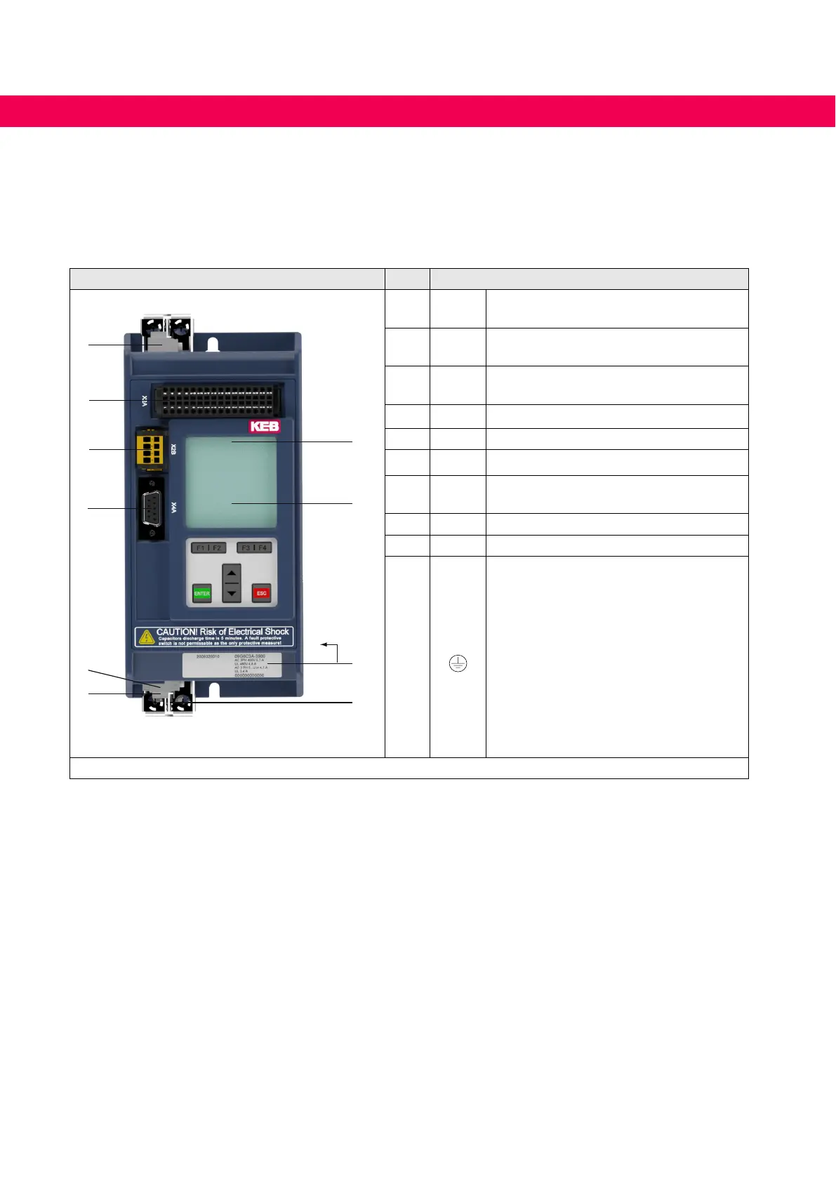
4.1 Overview of the COMBIVERT G6
Housing A No. Name Description
5
6
3
4
1
2
7
8
10
9
1
X1B
Terminal strip for three-phase motor ,
braking resistor and DC supply
2
X1C
Temperature monitoring; Connection for
external PTC or temperature switch
3
X4A
Diagnostic interface;
RS232/485 interface with DIN66019-II
4
X2B Safety function STO (optional)
5
X2A Control terminal strip 32 pole
6
X1A Mains input
7
LED1
Drive converter state
(if there is no operator)
8
– Operator with display and keyboard
9
– Type plate
10
PE,
Protective earth;
at connection to protective earth each
terminal may be assigned only once.
The shielding e.g. from the motor cable
is laid on the mounting plate in the
control cabinet or on the mounting kit
(optionally available).
See „Mounting kit for G6 housing A“.
Figure 6: Overview of the COMBIVERT G6
34
OVERVIEW OF THE COMBIVERT G6

 Loading...


