Model 2750 Multimeter/Switch System Service Manual Performance Verification 1-15
2750 Verification
3. Select the Model 2750 4-wire resistance function by pressing the 4 key, then
choose the SLOW integration rate with the RATE key.
4. Set the Model 2750 for the 1 range, and make sure the FILTER is on. Enable
OCOMP (offset-compensated ohms) by pressing SHIFT then OCOMP. (Use
OCOMP for 1, 10, and 100 range verification.)
5. Recalculate reading limits based on actual calibrator resistance values.
6. Source the nominal full-scale resistance values for the 1-10M ranges summa-
rized in Table 1-6, and verify that the readings are within calculated limits.
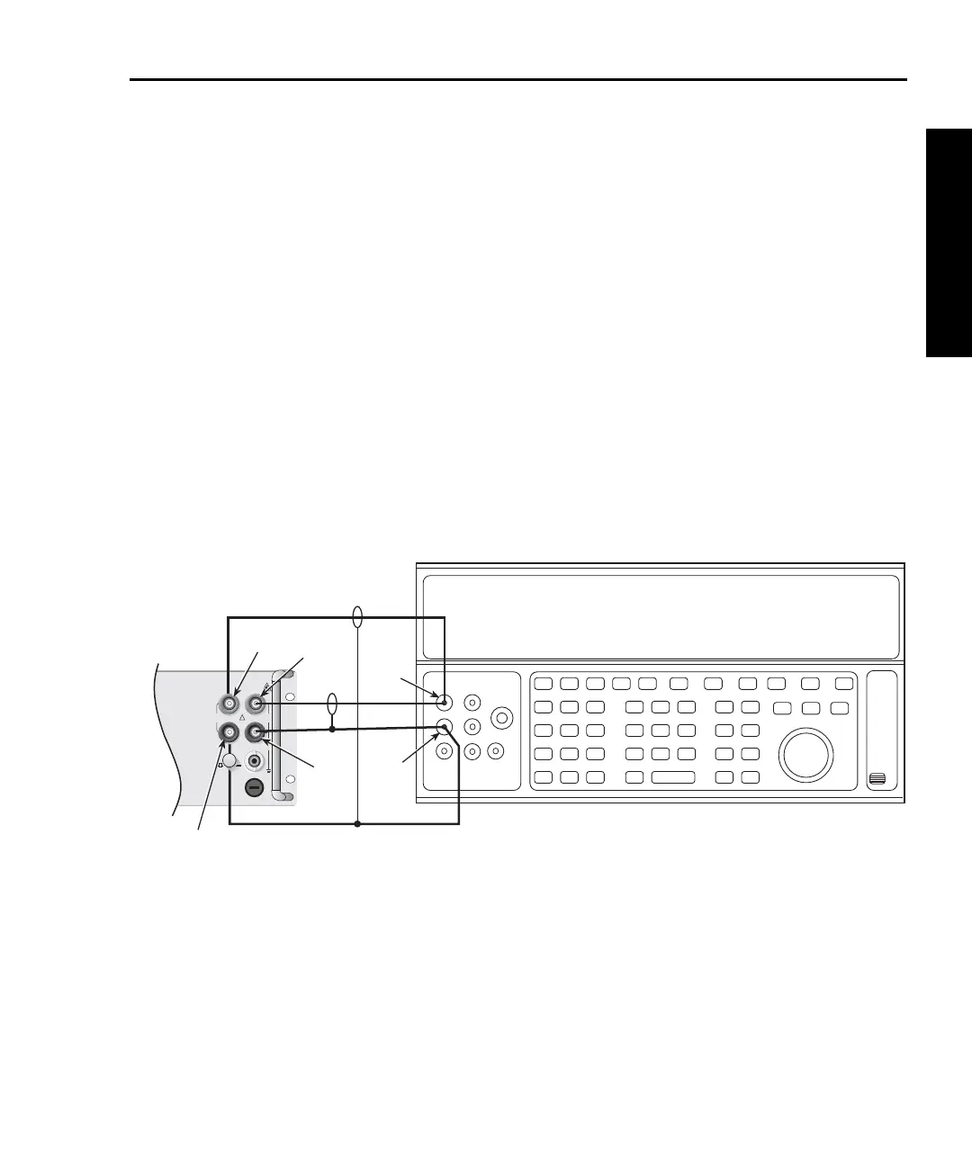
7. Connect the Model 2750 INPUT and SENSE jacks to the calibrator as shown in
Figure 1-6.
8. Disable external sense on the calibrator.
9. Set the Model 2750 for the 100M range.
10. Source a nominal 100M resistance value and verify that the reading is within cal-
culated limits for the 100M range.
Figure 1-6
Connections for Model 2750 resistance verification (100M range)
Input
HI
Input
LO
Output
LO
Output
HI
Calibrator (Output 2-wire Resistance)
Note: Use shielded cables to minimize noise.
Disable calibrator external sense mode.
Sense
LO
Sense
HI
!
F
500V
PEAK
FRONT/REAR
AMPS
HI
INPUT
LO
SENSE
Ω 4 WIRE
INPUT
350V
PEAK
1000V
PEAK
R
CAT I
Model 2750
Front Panel