, NOTE. LEAVE GREEN DISCONNECTED
! V. 0 GUdRD OFF
L- .-... .~.~..
---.~-..--- i
Figure 7-9. Connections for Ohms Calibration
(20k0 and 20MQ Ranges1
7.4.15 Voltage Source Calibration
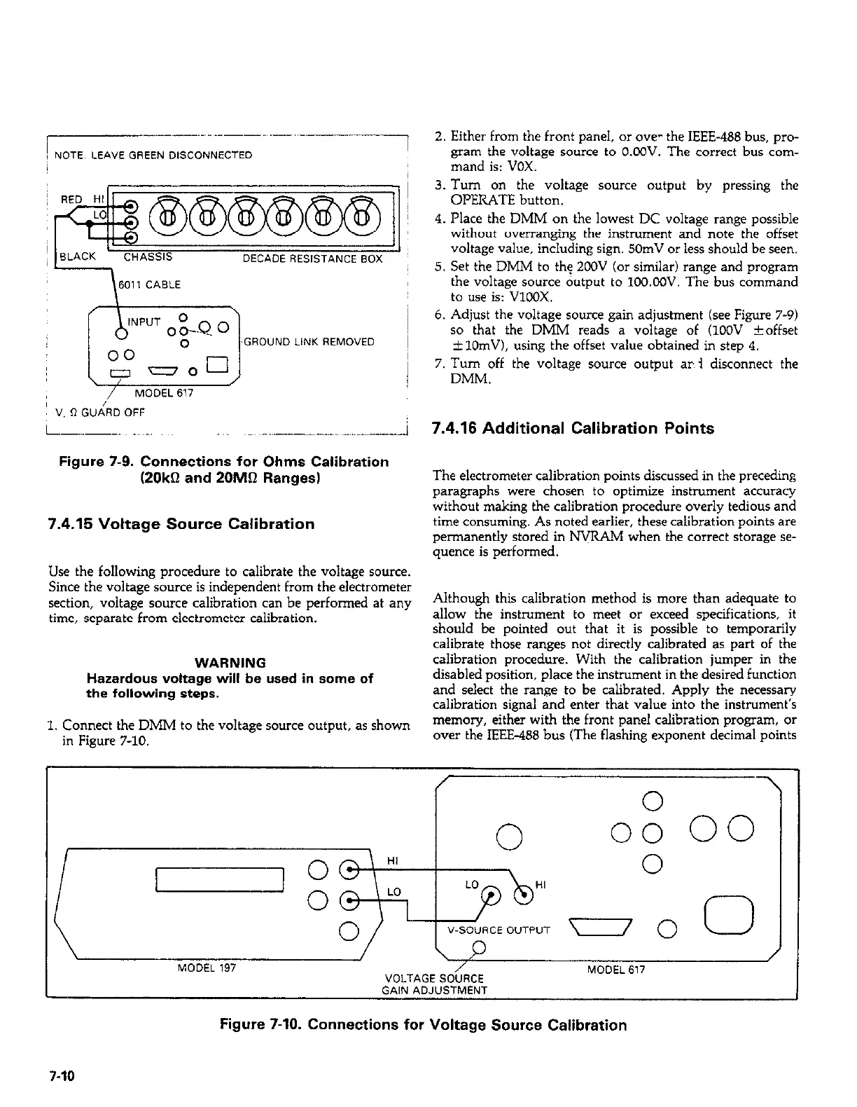
Use the following procedure to calibrate the voltage source.
Since the voltage source is independent from the electrometer
section, voltage source calibration can be performed at any
time, separate from electrometer calibration.
WARNING
Hazardous voltage will be used in some of
the following steps.
1. Connect the DMM to the voltage source output, as shown
in Figure 7-10.
2. Either from the front panel, or we- the IEEE-466 bus, pro-
gram the voltage source to O.OOV. The correct bus com-
mand is: VOX.
3. Turn on the voltage source output by pressing the
OPERATE button.
4. Place the DMM on the lowest DC voltage range possible
without overranging the instrument and note the offset
voltage value, including sign. 50mV or less should be seen.
5. Set the DMM to the ZOOV (or similar) range and program
the voltage source output to lOQ.CQV. The bus command
to use is: VlCOX.
6. Adjust the voltage source gain adjustment (see Figure 7-9)
so that the DMM reads a voltage of (KY&’ *offset
&lOmV), using the offset value obtained in step 4.
7. Turn off the voltage source output ar 3 disconnect the
DMM.
7.4.16 Additional Calibration Points
The electrometer calibration points discussed in the preceding
paragraphs were chosen to optimize instrument accuracy
without making the calibration procedure overly tedious and
time consuming. As noted earlier, these calibration points are
permanently stored in NVRAM
when the correct storage se-
quence is performed.
Although this calibration method is more than adequate to
allow the instrument to meet or exceed specifications, it
should be pointed out that it is possible to temporarily
calibrate those ranges not directly calibrated as part of the
calibration procedure. With the calibration jumper in the
disabled position, place the instrument in the desired function
and select the range to be calibrated. Apply the necessary
calibration signal and enter that value into the instrument’s
memory, either with the front panel calibration program, or
over the IEEE-488 bus (The flashing exponent decimal points
/
MODEL 197
VOLTAGE SOURCE
MODEL 617
GAIN ADJUSTMENT
Figure 7-10. Connections for Voltage Source Calibration
7-10